________________________________________________________________________________________________________________
12-20-2002
Figure Sheet 1-853-A
Page 22
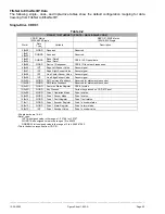
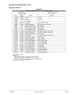
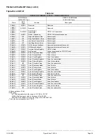
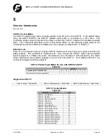
FifeNet to EtherNet/IP Data
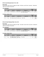
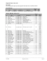
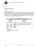
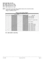
The following single-, dual-, and triple-drive tables show the default configuration mapping for data
traveling from FifeNet to EtherNet/IP.
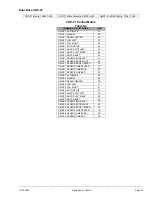
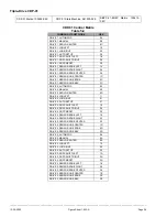
Single-Drive CDP-01
Table 4-2
FIFENET TO ETHERNET / IP DATA – SINGLE-DRIVE CDP-01
CDP-01 Matrix
100246-02X Single
SBPC-21-EN/IP Matrix
100410-02X Single
Word
1
Data
Type
2
Variable Description
0 (0x00)
WORD Reserved
Reserved.
1 (0x01)
2 (0x02)
DWORD Reserved
Reserved.
3 (0x03)
4 (0x04)
DWORD
Panel Data 0
Panel Data 1
CDP-01 LED panel data.
5 (0x05)
WORD
Device 1 Response
3
CDP-01 Fife network responses.
6 (0x06)
INT
Edge Left Sensor Value
Sensor signal.
7 (0x07)
INT
Edge Right Sensor Value
Sensor signal.
8 (0x08)
INT
Line Center Sensor Value
Sensor signal.
9 (0x09)
INT
Line Edge Sensor Value
Sensor signal.
10 (0x0A)
WORD
SM Command Feedback
Reserved for state machine control.
11 (0x0B)
WORD
SM Status Feedback
Reserved for state machine control.
12 (0x0C)
WORD
Common Status Register
CDP-01 status.
13 (0x0D)
WORD
Key Pressed
Current key pressed on CDP-01 Panel.
14 (0x0E)
WORD
Drive 1 Operation Mode
Drive 1 status.
15 (0x0F)
WORD
Drive 1 Sensor Mode
Drive 1 status.
16 (0x10)
WORD
Drive 1 Fault Register
Drive 1 fault status.
17 (0x11)
WORD
Drive 1 Encoder Register
Drive 1 encoder status.
18 (0x12)
WORD
Drive 1 Alarm Register
Drive 1 alarm status.
19 (0x13)
INT
Drive 1 Encoder Value
Drive 1 encoder value.
1
All data words are 16-bit
2
Data Types:
INT 16-bit signed value in the range of –32,768 to +32,767.
WORD 16-bit unsigned value in the range of 0 to 65,535.
DWORD 32-bit unsigned value in the range of 0 to 4,29,4967,295.
3
This is the device response from CDP-01.

