3.0 SYSTEM COMPONENTS
UL S2203
Cheetah Xi Install ation Manual
3-3
FM
P/N: 06-356
Rev 9, 10/2016
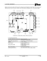
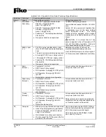
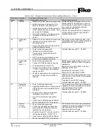
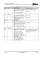
Exhibi t 3-5: Cheetah Xi Contro ller Terminal Specificatio ns
Terminal
Block
Terminal
Labels
Function and Electrical
Ratings/Requirements
Wiring Requirements
P1
AC XFMR
Secondary
120 VAC Transformer P/N 02-10881
Standby = 3A @ 25.35 VAC
Alarm = 6A @ 25 VAC
240 VAC Transformer P/N 02-10882
Standby = 3A @ 25.4 VAC
Alarm = 6A @ 25 VAC
Fused by F1, 15A field replaceable fuse,
P/N 02-4174
Non-power limited and supervised
16 AWG THHN wiring minimum
Terminal block accepts 12 AWG – 16 AWG
wire
System AC Line power must originate from
a dedicated circuit at the main building
power distribution center.
The circuit
breaker shall be equipped with a lockout
mechanism and be clearly labeled as a “Fire
Alarm.”
CAUTION:
It is critical that AC line
power is applied to the left terminals of P1
and not the battery terminals. Doing so
could cause damage to the controller.
Battery Input
(+ -)
24 VDC nominal standby battery input
(Two 12 VDC batteries, sealed lead acid
only)
75 amp-hour maximum charging capacity
4 Amps @ 27 VDC max. charge current
12 Amps @ 27 VDC max. supply current
Fused by F2, 15A field replaceable fuse,
P/N 02-4174
Non-power limited and supervised
Batteries larger than 18 AH must be
mounted in external battery enclosure.
Use 14 AWG minimum wire (max. length of
10 ft. [3m] to connect batteries to controller)
P2
Alarm
(Relay 1)
Terminals C, NC, NO
SPDT Form C relay contact
DC Operation: 2 amps @ 30 VDC (pf-.35)
AC Operation: 0.5 amps @ 120 VAC
(pf=.35)
Default alarm operation (configurable)
All connections shall be power limited or
non-power limited, not both
Supervisory
(Relay 2)
Terminals C, NC, NO
SPDT Form C relay contact
DC Operation: 2 amps @ 30 VDC (pf-.35)
AC Operation: 0.5 amps @ 120 VAC
(pf=.35)
Default supervisory operation
(configurable)
All connections shall be power limited or
non-power limited, not both
Troube
(Relay 3)
Terminals C, NC, NO
SPDT Form C relay contact
DC Operation: 2 amps @ 30 VDC (pf-.35)
AC Operation: 0.5 amps @ 120 VAC
(pf=.35)
Default trouble operation
All connections shall be power limited or
non-power limited, not both
Relay contacts are normally energized and
contacts are shown with power applied and
no Troubles present on the s ystem.
P3
Computer
RS232 port, power limited and supervised
Used for panel programming, peripheral
device configuration, and data retrieval
using C-Linx software
Not intended for continuous connection
Do not connect the PC if a ground fault is
present on the controller
Use communication cable P/N 10-1874A or
B to connect programming computer to P3
50 ft. (15m) maximum cable length.
PC communication: 19200 Baud, 8 data
bits, no parity, 1 stop bit

