3.0 SYSTEM COMPONENTS
3-6
Cheetah Xi Instal latio n Manual
UL S2203
Rev 9, 10/2016
P/N: 06-356
FM
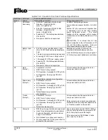
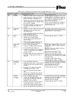
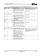
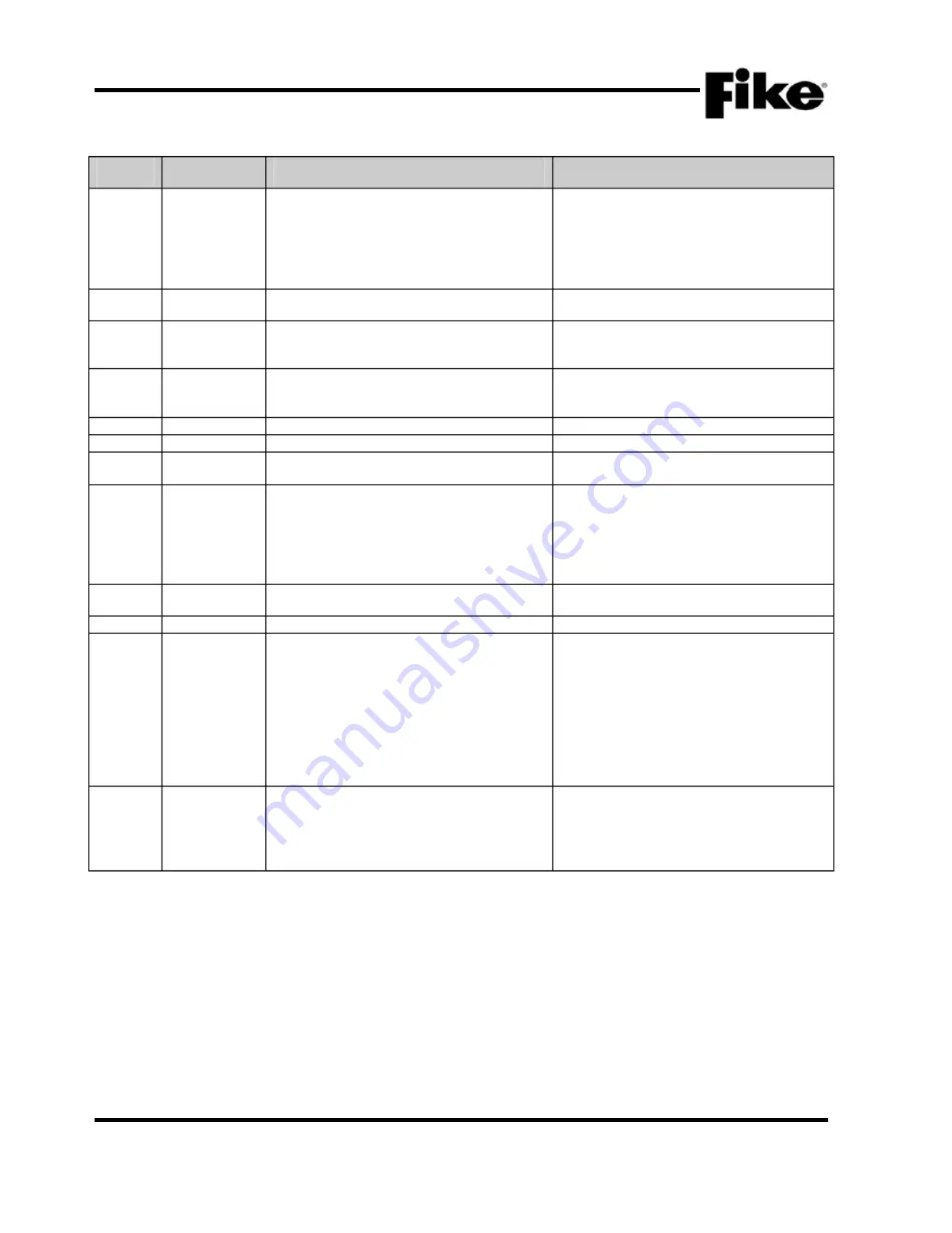
Exhibi t 3-8: Cheetah Xi Contro ller Termin al Specifi cation s – Cont.
Terminal
Block
Terminal
Labels
Function and Electrical
Ratings/Requirements
Wiring Requirements
P13
Provides connection point for an optional
CRM4 relay module (P/N 10-2204) or an
RPM reverse polarity module (P/N 10-
2254)
If P20 is occupied by a Network module,
the P13 terminal is not available
All CRM4 connections shall be power
limited or non-power limited, not both
See Section 4.11
P14
No
Connection
P15
Connects optional Supplemental Loop
Module, P/N 10-2473 to the Cheetah Xi
controller
See Section 4.11
P16
Connects optional Supplemental Power
Supply Module, P/N 10-2474-P to the
Cheetah Xi controller
See Section 4.11
P17
For Fike use only
P18
For Fike use only
P19
Controller display interface (keypad and
LEDs)
P20
Provides connection point for an optional
RS485 network module (P/N 10-2482) or
Fiber Optic network module (P/N 10-
2624)
If P13 is occupied by a CRM4 or RPM
module, the P20 terminal is not available
See Section 4.11
P21
No
Connection
P22
Controller display interface (LCD only)
TP1
Cheetah Xi controller ground reference
test point
Use when making DC voltage
measurements on the control board
Normal ground fault limits (TP1 to
Chassis): 2.17 VDC nominal for Level 1
and 5 VDC nominal for Level 2. If a
ground fault is present, voltage will sway
in either direction.
Ground fault detection impedances are 60K
Ω
between power ground and chassis
ground or 1M
Ω
between main power and
chassis ground
TP2
Positive (+) side of the Cheetah Xi
controller 24 VDC power bus
To verify controller voltage, connect
positive lead of voltmeter to TP2 and
ground lead of voltmeter to TP1

