3.0 SYSTEM COMPONENTS
3-8
Cheetah Xi Instal latio n Manual
UL S2203
Rev 9, 10/2016
P/N: 06-356
FM
3.4
OPTIONAL CIRCUIT MODULES
Several optional circuit modules can be installed onto the Cheetah Xi controller to expand its operational
capabilities. A brief description of each module and its functionality is provided in this section for reference
purposes. For a complete description of each module’s functionality, installation and wiring, refer to the
devices installation sheet.
3.4.1
DACT, 5 ZONE WITH SERIAL INTERFACE
P/N 10-2528 (BOSCH FPT-DACT-LC), INTERNAL MOUNT
P/N 10-2476 (BOSCH FPT-DACT), EXTERNAL MOUNT
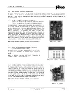
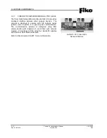
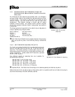
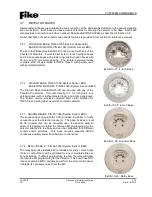
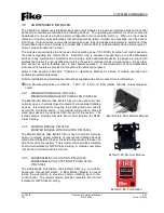
The Digital Alarm Communicator Transmitter (See Exhibit 3-11) is
used where point identification of alarm, supervisory and trouble
events is required at a Central or Remote Receiving Station. The
Cheetah Xi transmits all system information to the DACT via an
RS485 connection.
In addition, the DACT includes five
programmable point inputs that can be individually configured to
indicate seven types of system conditions: Fire Alarm, Waterflow
Alarm, Supervisory, Monitor Alarm, System Fault, AC Failure and
Low Battery. These inputs can be used in place of the intelligent
RS485 connection to provide simple alarm monitoring where the
receiving station is not capable of receiving point ID information.
Refer to Fike document 06-479, for further more information.
3.4.1.1 DACT KEYPAD PROGRAMMER, P/N 10-2477
(BOSCH FMR-DACT-KEYPAD)
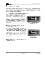
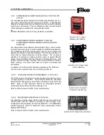
This DACT Programmer (See Exhibit 3-12) is necessary for
configuring the 10-2528 and 10-2476 dialers referenced
above.
Refer to BOSCH document FPT-DACT “Operation &
Installation Guide” for more information.
3.4.2
SUPPLEMENTAL POWER SUPPLY (SPS), P/N 10-2474-P
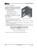
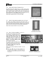
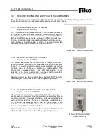
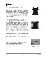
The Supplemental Power Supply (See Exhibit 3-13) can be added to
a base Cheetah Xi 1016 system to double the power capacity. It
includes a power supply circuit board and secondary transformer (-1
for 120VAC primary; -2 for 240VAC primary), which adds 2A external
standby power and 6A alarm power to the system. This increases
the total system power to 4A standby / 12A alarm total. The SPS
interfaces to P16 on the Cheetah Xi controller behind the LCD using
the four standoffs and hardware supplied with the SPS.
Refer to Fike document 06-340, for further more information.
Exhibi t 3-13: SPS
Exhibi t 3-12: DACT Programm er
Exhibi t 3-11: DACT

