3.0 SYSTEM COMPONENTS
UL S2203
Cheetah Xi Install ation Manual
3-13
FM
P/N: 06-356
Rev 9, 10/2016
3.5.6
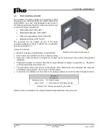
INTELLIGENT GRAPHIC ANNUNCIATOR
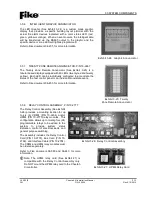
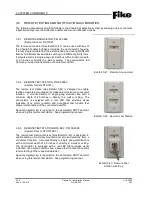
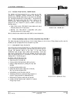
The LED Graphic (See Exhibit 3-24) is a custom made graphic
display that provides a specific building layout pictorial with the
actual fire alarm devices indicated with a color status LED (red,
green, yellow or orange). When an event occurs, the intelligent data
will be transferred via the RS485 output to the graphic and the
specific device or zone LED will light as programmed.
Refer to Fike document 06-231, for more information.
3.5.7
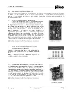
TWENTY ZONE REMOTE ANNUNCIATOR, P/N 10-2667
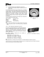
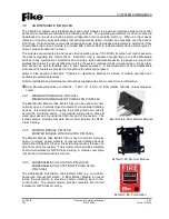
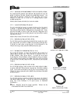
The Twenty Zone Remote Annunciator (See Exhibit 3-25) is a
tabular based display equipped with 40 LEDs (twenty red and twenty
yellow). Each LED can be individually configured to annunciate the
status of the host control panel or an individual zone/state event.
Refer to Fike document 06-453, for more information.
3.5.8
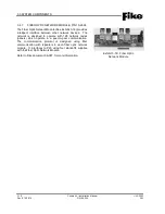
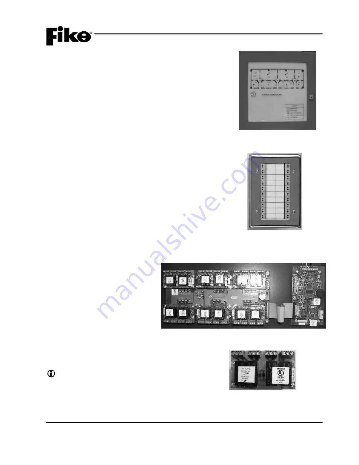
RELAY CONTROL ASSEMBL Y, P/N 10-2777
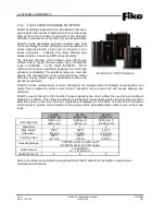
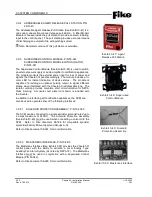
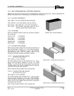
The Relay Control Assembly (See Exhibit
3-26) provides a mounting location for up
to six (6) CRM4 (P/N 10-2204) and/or
HPM4 (P/N 10-2770) relay modules. This
configuration allows up to twenty-four (24)
programmable relays to be added to the
system
to
provide
system
status
indication, control of electrical loads, and
general purpose switching.
The assembly includes the Relay Control
Card (P/N 10-2778), Bus Card (P/N 10-
2769), and Interface Cable (P/N 10-2784).
The CRM4 and HPM4 relay modules must
be ordered separately.
Refer to Fike document 06-580 and 06-443, for more
information.
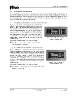
Note:
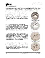
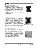
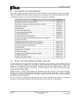
The HPM4 relay card (See Exhibit 27) is
compatible with the Relay Control Assembly only.
Do NOT mount the HPM4 relay card to the Cheetah
Xi controller.
Exhibit 3-24: Graphic Annunc iator
Exhibit 3-25: Twenty
Zone Remote Ann unciator
Exhibit 3-26: Relay Control Ass embly
Exhi bit 3-27: HPM4 Relay Card


