4.0 INSTALLATION
4-2
Cheetah Xi Instal latio n Manual
UL S2203
Rev 9, 10/2016
P/N: 06-356
FM
4.3
SELECT THE ENCLOSURE MOUNTING OPTION
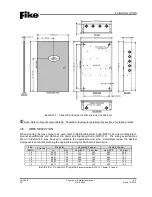
The system enclosure is designed to be surface or flush mounted. For surface mounting, you will utilize the
mounting holes provided in the back of each enclosure to secure it to the wall. For flush mounting, you will
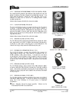
need to cut an opening in the wall to fit the back-box dimensions (See Exhibit 4-1) and secure the enclosure
in place by utilizing the through holes located on the sides of the box. The enclosure is designed to fit
between wall framing members for flush mounting.
Note:
The Cheetah Xi enclosure is NOT fire rated; do not install on or in fire rated walls unless steps are
taken to maintain the fire rating of the wall.
4.4
MOUNT THE ENCLOSURE
The following general steps shall be used to install the system enclosure:
1. Disconnect the grounding wire from the enclosure door by unscrewing the hex-nut.
2. Remove the enclosure door by unscrewing the two hinge screws.
3. Determine the maximum number of conductors needed from the design and punch out the
appropriate conduit knockouts. All field wiring is to be routed into the enclosure via knock-out
openings. Conduit knock-outs are provided for two distinct conduit sizes. Removing just the inside
hole creates a one-half inch (1/2”) opening. Removing the entire opening provides a three-quarter
inch (3/4”) opening.
Note:
Unless otherwise detailed in this manual or in other documents relating to this control
panel, the technician shall utilize published standards and references such as NFPA 70 National
Electrical Code, NFPA 72 National Fire Alarm Code, and others, which may be relevant to the
Local Authority Having Jurisdiction for selecting the appropriate conductor size and quantity.
Note:
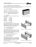
If batteries are to be installed in the enclosure, do not use the conduit knock-outs in the
bottom of the enclosure.
4. For surface mounting, mark and pre-drill holes in mounting surface and secure the back-box to the
wall using appropriate mounting hardware.
5. For flush mounting, mark and cut an opening in the wall to fit the back-box dimensions (See Exhibit 4-
1). Wall must be framed to accommodate the back box dimensions. Secure the enclosure in place
by utilizing the through holes located on the sides of the box.
6. Re-install the outer door onto the enclosure.
7. Re-connect the grounding wire to the enclosure door. Check for continuity between door and back-
box to complete the installation.
Note:
Refer to the installation instructions supplied with the enclosure for further details.


