4.0 INSTALLA TION
UL S2203
Cheetah Xi Install ation Manual
4-7
FM
P/N: 06-356
Rev 9, 10/2016
4.11 INSTALL OPTIONAL MODULES
Several optional circuit modules can be installed onto the Cheetah Xi controller to expand its operational
capabilities. The modules contain static sensitive components; therefore, handle them by the edges only and
avoid touching the integrated components. Keep each module in the protective static bag it was shipped in
until time for installation. Always ground yourself with a proper wrist strap before handling the module(s) to
reduce the risk of damage due to static discharge.
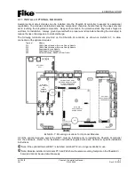
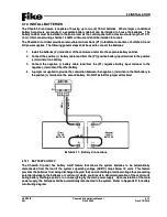
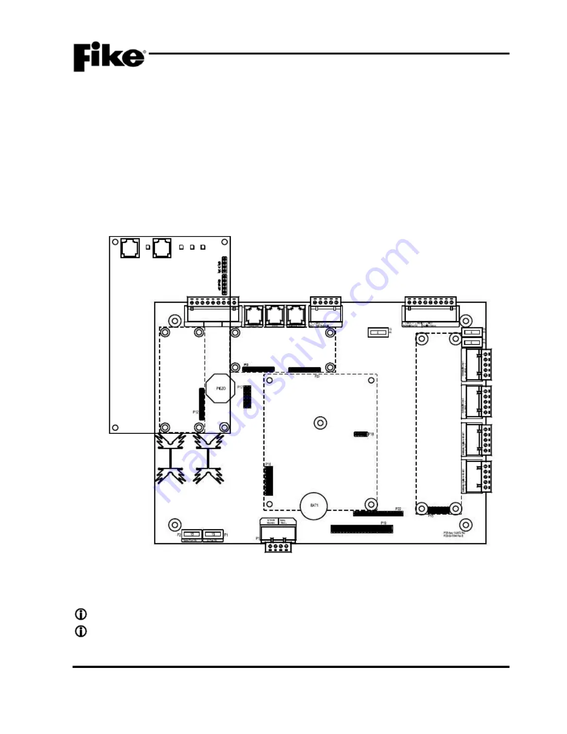
The following terminals are provided on the Cheetah Xi controller, as shown on Exhibit 4-7, to allow
connection of the optional modules:
Terminal
Module
P12
CRM4 Relay Module or Reverse Polarity Module
P13
CRM4 Relay Module or Reverse Polarity Module
P15
Supplemental Loop Module
P16
Supplemental Power Supply
P20
Network Modules (RS485 or Fiber Optic)
All of the optional modules, except the DACT, must be installed prior to installing the Cheetah Xi controller
into the enclosure. Refer to the installation instructions supplied with each module for specific installation
instructions.
Note:
If the optional Internal DACT is installed, terminal P12 is no longer availa ble for use.
Note:
Modules installed in terminals P13 and P20 share the same mounting footprint on the Cheetah Xi
board and cannot be used simultaneously.
P7
C NC NO
Alarm
P11
P10
P9
P8
P6
P2
C NC NO
Supervisory
C NC NO
Trouble
L
I
N
E
2
S
Y
S
T
R
B
L
H
E
A
R
T
B
E
A
T
L
I
N
E
1
OPTIONAL
DACT
OPTIONAL
CRM4 RELAY
OR
REVERSE
POLARITY
MODULE
OPTIONAL CRM4 RELAY,
NETWORK MODULES (RS485
& FIBER), OR REVERSE
POLARITY MODULE
OPTIONAL
SUPPLEMENTAL
POWER SUPPLY
OPTIONAL
SUPPLEMENTAL
LOOP MODULE
Exhibit 4-7: Mounting Locations for Optional Modules

