EQUIPMENT
FIKE CORPORATION
Page 10 of 43
SHP Product Manual
UL S2203
Rev. No: 3, 04/02
Manual P/N: 06-130
FM 0Z8A0.AY
•
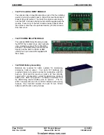
10-2172 CLASS A INPUT MODULE
The optional Class A Input Module allows any of the four initiating
device circuits to be wired Class A (Style D) versus the standard
Class B (Style B) method. The Class A module mounts directly
onto the SHP Controller utilizing four stand-offs supplied with the
module. If used, any of the four circuits wired as Class B rather
than Class A, shall have the pertinent resistor (R1-R4) removed
from that circuit.
•
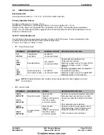
10-2176 SRM4 RELAY MODULE
The optional SRM4 Relay Module provides
four DPDT dry contact relays, which activate
upon selected events per the configuration
switches. The SRM4 Relay module mounts
directly onto the SHP Controller at RM4
utilizing four nylon stand-offs supplied with
the module.
•
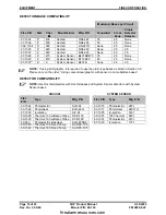
10-2190-B Battery Assembly
Batteries are required for alarm systems for maintaining
emergency back-up power. Two each 12V batteries are
required and are to be wired in series for maintaining a 24VDC
back-up. Most systems require at least a 24 hour standby
current with 5 minutes alarm current for determining minimum
battery size. Refer to Appendix 1 for Battery Calculation form
for determining required battery size for system. The 10-
2190-1 consists of 2 each 7A-H, 12VDC batteries with a wiring
harness. The 10-2190-2 consists of 2 each 18 A-H, 12VDC
batteries with the same wiring harness.
firealarmresources.com
Summary of Contents for SHP 10-051
Page 2: ...firealarmresources com ...
Page 4: ...firealarmresources com ...
Page 48: ...firealarmresources com ...
Page 50: ...firealarmresources com ...
Page 51: ...firealarmresources com ...


