INSTALLATION
FIKE CORPORATION
Page 22 of 43
SHP Product Manual
UL S2203
Rev. No: 3, 04/02
Manual P/N: 06-130
FM 0Z8A0.AY
4.2
POWER AND FIELD WIRING
Field Wiring / Power Limited Requirements:
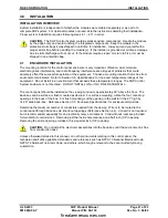
Route all field wiring through the appropriate conduit knockouts. Provide adequate wire length for strain
relief. SHP terminal blocks (including SRM4 and Class-A modules) accept single wire from 14 to 30
AWG.
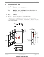
SHP left side (P1) connections including AC Power, Auxiliary Power In, and Battery power are non-power
limited and shall be routed only in the enclosure’s left side.
SHP top (P2 & P3) and right side (P4) connections are power limited and shall not be routed within 2” of
the enclosure’s left side to ensure segregation from the non-power limited wiring.
When planning the type of wire to be used, refer to National Electrical Code, NFPA 70. This information
was derived from the 1993 edition. Stranded wire shall be tinned per NFPA70 and local requirements.
AWG
Stranding
Nominal
Diameter
Uncoated Copper
(
Ω
s /1000’)
Coated Copper
(
Ω
s /1000’)
18
solid
0.040”
7.77
8.08
18
7
0.046”
7.95
8.45
16
solid
0.051”
4.89
5.08
16
7
0.058”
4.99
5.29
14
solid
0.064”
3.07
3.19
14
7
0.073”
3.14
3.26
Abort Switch Wiring Criteria:
Abort input circuits are to be wired only with momentary contact switches so they cannot be left activated
without human interaction.
AC Power & Chassis Wiring
:
AC power must originate from a dedicated 10 - 20 amp circuit at the main building power distribution
center. The circuit breaker must be equipped with a lockout mechanism and be clearly labeled as a “Fire
Protection Control Circuit.”
Ensure the power to be used is compatible with the transformer assembly (120VAC or 208/240VAC).
Route the AC hot, neutral, and ground (chassis) wires into the enclosure and connect to the AC Power
strip per the wiring diagram at the beginning of this section. For 120VAC operation, connect the three
wires directly to the terminal block. For 208/240 operation, connect the AC hot and AC neutral to the
appropriate terminal block connection, but connect ground chassis to the chassis standoff. When
completed, verify continuity from chassis (green wire) to enclosure and to conduit.
NOTE:
Complete wiring with AC power off and locked-out. Likewise, remove F1 fuse from the
controller board to ensure the battery packs cannot provide system power until wiring is
completed and system is ready for checkout. Do not attach any gas cartridge actuators or other
non-reversible electrical devices until the system has been proven to be fully operational.
firealarmresources.com
Summary of Contents for SHP 10-051
Page 2: ...firealarmresources com ...
Page 4: ...firealarmresources com ...
Page 48: ...firealarmresources com ...
Page 50: ...firealarmresources com ...
Page 51: ...firealarmresources com ...

