FIKE CORPORATION
INSTALLATION
UL S2203
SHP Product Manual
Page 27 of 43
FM 0Z8A0.AY
Manual P/N: 06-130
Rev. No. 3, 04/02
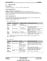
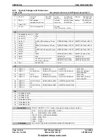
SW3 CONFIGURATION
The operation characteristics of the SHP system is determined by the configuration dip switches located
on the SHP Controller (SW3). These switches allow you to field define the operation of the SHP.
NOTE:
Bold values indicate default positions (0001 1000 01) in S1 to S10 order. 0=off. Default
position only has switch positions S4, S5, & S10 on. All others are off.
Switch
Position
0 = Off
1 = On
Operational Characteristic
S1
0
1
Suppression System Mode
Sprinkler System Mode
S2
0
1
Sequential Alarm Detection
Cross-Zone Detection
S5/S6
0/0
0/1
1/0
1/1
Pre-discharge Delay
= 00 Seconds
= 15 Seconds
= 30 Seconds
= 60 Seconds
S8
0
1
Pre-discharge / Sequential Alarm options per Table 4.7
Supervisory / Manual Release options per Table 4.7
S9
0
Unused (leave in the off position)
S10
0
1
Auxiliary 24 volt power input supervised
Auxiliary 24 volt power input supervision disabled
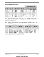
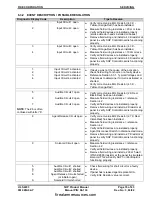
Dip switch positions S3, S4 and S7 allow you to adjust certain characteristics of the SHP panel as it
pertains to each operational mode (suppression versus sprinkler). The function of these switches varies
according to the setting of dip switch S1.
Switch
Position
0 = Off
1 = On
Suppression Mode (S1 = Off)
Sprinkler Mode (S1 = On)
S3/S4
0/0
0/1
1/0
1/1
Abort Type
(see appendix A
for description of
abort types).
= 1
= 2
= 3
= 4
Solenoid On
Time
= Continuous
= 4-5 Min.
= 9-10 Min.
= 29-30 Min.
S7
0
1
ARM-III Operation
12 volt solenoid operation
Not Applicable (Unused)
ABORT TYPES:
These abort types are programmable via SW3 configuration switches S3-S4. Countdown does not begin
until the system is in the predischarge state.
TYPE 1:
The abort is effective only if active upon entry into predischarge state. Countdown continues
during abort activation. Upon abort deactivation (during predischarge), the release cannot again be aborted,
so release occurs upon countdown completion.
Conforms to Industrial Risk Insurers (IRI) requirements.
TYPE 2:
Countdown continues during abort activation. Release occurs when both the countdown is
completed and the abort is deactivated.
TYPE 3:
If the abort is active during predischarge, release occurs upon abort deactivation.
TYPE 4:
Upon abort deactivation, countdown occurs from the full programmed countdown time. Prior to
countdown completion, abort activation extends the countdown time to the programmed length. Does not
conform to UL requirements, but is allowed by some Local Authority having Jurisdiction. Type 4 with “0”
countdown also provides “NYC mode” as described in the note below.
NOTE:
The ABORT switch delays releases initiated by automatic detection schemes. Releases
initiated by activated Manual Release input circuits override the Abort Switch.
NOTE:
For Abort = 4 with countdown = 00, system operates in “NYC mode” with a 120 second
verification delay, then a 30 second countdown after each abort input deactivation. During the
120 second verification delay, the system emulates continuous abort activation. After the 120
second delay, the system starts a 30 second pre-discharge delay.
firealarmresources.com
Summary of Contents for SHP 10-051
Page 2: ...firealarmresources com ...
Page 4: ...firealarmresources com ...
Page 48: ...firealarmresources com ...
Page 50: ...firealarmresources com ...
Page 51: ...firealarmresources com ...


