FIKE CORPORATION
APPENDIX 1
UL S2203
SHP Product Manual
Page 37 of 43
FM 0Z8A0.AY
Manual P/N: 06-130
Rev. No: 3, 04/02
APPENDIX 1
BATTERY CALCULATIONS
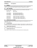
The SHP is designed for use with either of two battery packs. Each battery pack contains two 12V batteries
which can be installed in the SHP enclosure. Battery back-up duration must be extended for sprinkler
supervisory systems. Minimum battery capacity must exceed (by more than 10%) normal operation power
followed by alarm operation power for these durations:
Operation Type
Normal Operation
Alarm Operation
Local & Sprinkler Supervisory
90 hours
5 minutes
Auxillary or Remote Station
60 hours
5 minutes
Local Operation Only
24 hours
5 minutes
Each battery pack’s maximum current consumption for normal operation is:
---Max Normal Operation Current---
Battery Pack
Description
24 hour back-up 90 hour back-up
10-2190-1
7 Amp-Hour Battery Pack
0.260 A
Not applicable
10-2190-2
18 Amp-Hour Battery Pack
0.590 A
0.171 A
“Total normal current” and “total alarm current” can each be calculated as the sum of:
A.) SHP controller current
B.) SRM4 current for relays activated while in alarm
C.) Output current to activated indicating devices.
D.) Auxiliary current from Aux Power Out circuit.
Module Type:
Module Current Consumption
10-2171 Controller
0.090 Amps
10-2172 Class-A Module
0.000 Amps
10-2176 SRM4 Module
0.000 Amps (0.100A while in alarm)
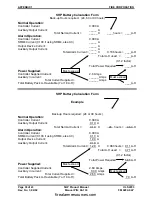
Normal operation power (in Amp-Hours) = (total normal current) X (24, 60, or 90 hours).
Alarm operation power = (total alarm current) X (0.0833 hours).
The selected battery capacity must exceed the sum of the Normal and Alarm power plus a 20% battery
power derating safety margin to ensure adequate system voltages are maintained. If using an
uninterruptable power supply that supplies power in excess of the above time durations; NFPA 72 allows
lesser amounts of system internal battery capacity.
NOTE:
The SHP 0.090 Amp current includes power to activate the normally energized trouble relay
and power for the maximum number of two wire detectors. The SRM4’s 0.100 Amps alarm current
is for the activated relays.
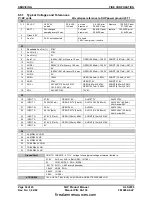
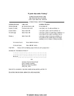
The following page includes a battery calculation form and illustrates a typical battery calculation example.
firealarmresources.com
Summary of Contents for SHP 10-051
Page 2: ...firealarmresources com ...
Page 4: ...firealarmresources com ...
Page 48: ...firealarmresources com ...
Page 50: ...firealarmresources com ...
Page 51: ...firealarmresources com ...


