04/14
MI-IR-EN-05
© by FILSA
IR
Talleres Filsa, S.A.U.
www.filsa.es
•
•
•
•
•
E-08100 Mollet del Vallès (Barcelona)
Tel.
+34 93 570 46 01
Fax
+34 93 570 24 71 filsa@filsa.es
05
130
130
200
200
68
60
60
10
50
125 or 180
60
220
30
60
30
30
30
2.
Installation
2.1 Preparing for use
-
- Verify if you got all the parts, the controller, blade with pin and
shaft extension if it was requested.
Read the Safety instructions and the Operating instructions before
using the controller.
2.2
Mechanical connection
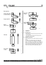
There are models that can be mounted horizontally or vertically into
the silo.
The standard form is mounting the device with a flange, drilling
holes on the silo to allow the mounting of the controller using
screws, rods, fasteners or nuts. If the flange was not requested, the
thread is G 1 " 1/4 and can be fixed using 1 or 2 nuts or introducing
it into a threaded socket with a maximum of 25 mm length. If it is
larger, the bulk goods have the possibility to deposit in the thread
socket. This could provoke that the device becomes useless.
IR-019
IR-020
IR-021
IR-022
IR-024
IR-025
125 or 180
10
50
IR-023
70
70
60
100
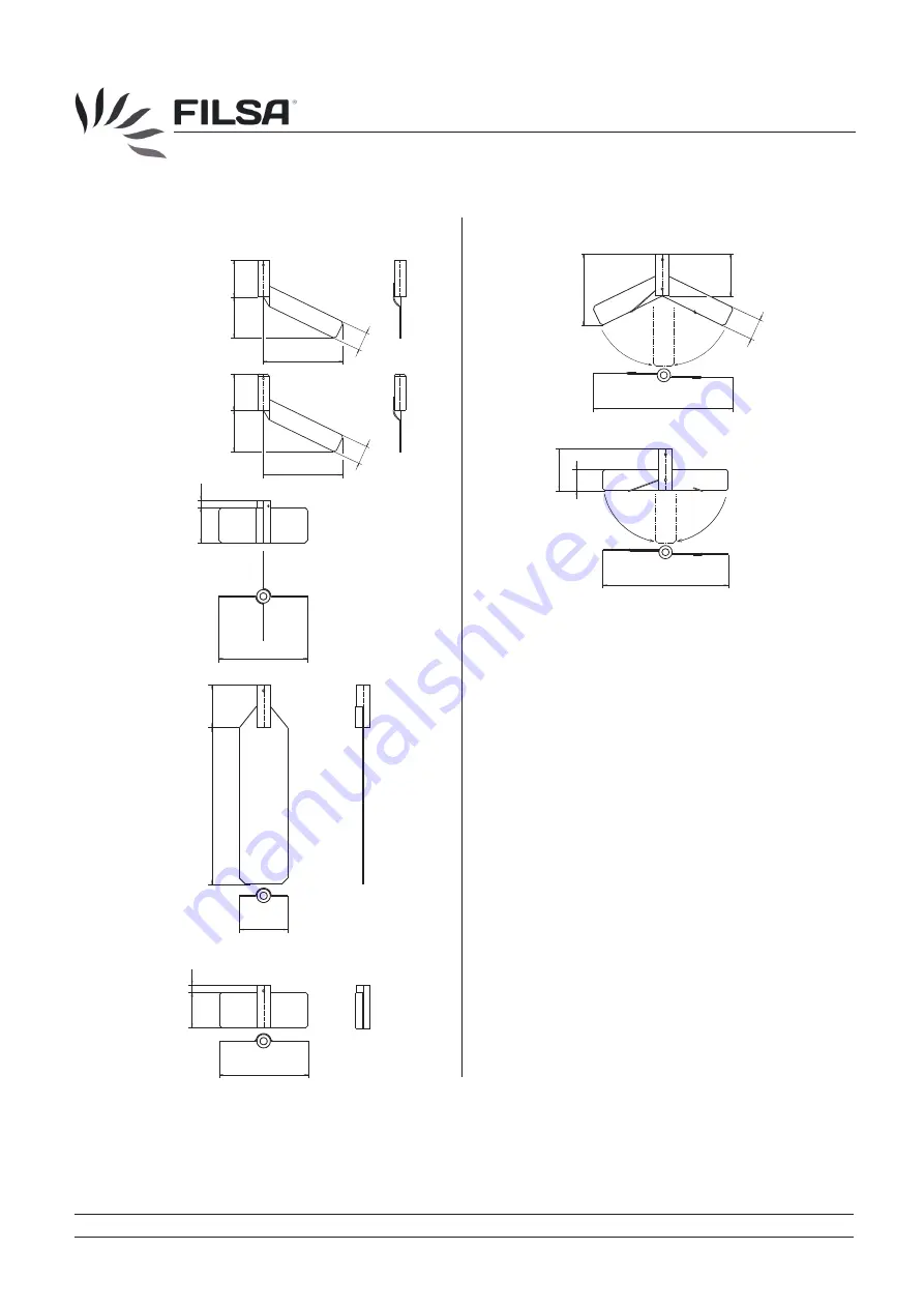
Measuring blades
Diagonal blade IR-DR
and models with shaft
Diagonal blade IR-D
Blade X
IR-125 or IR-180
IR-69 blade
Hinged blade
Y 30x200
Hinged blade
T 30x200
Blade T IR-125
or IR-180


