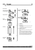
Protection roof
2.3
Electrical connection
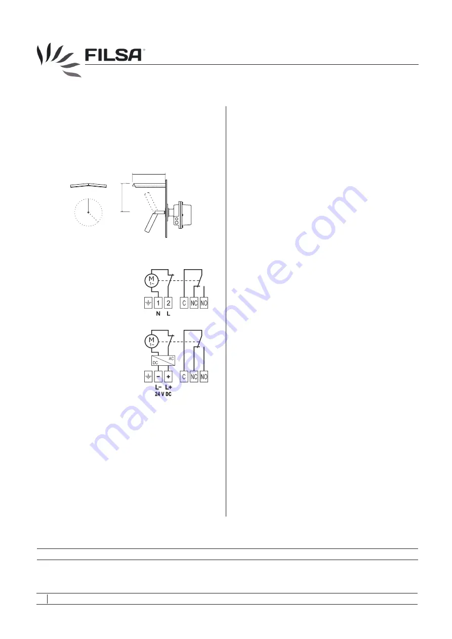
Connection diagram AC
Connection diagram DC
Cable gland
- Fasten the cable gland after making the electrical connection.
- Fix and fasten the screw nut of the cable gland to make sure of
the water-tightness.
3.
Use
3.1
Commissioning
- Put the controller into operation only if the installation and the
electrical connection have been done correctly.
-
The blade must not be hit by the filling stream. To avoid this,
deflect the filling stream or install a deflection screen or a
protection roof. It is also recommended to install a protection roof
when the controllers are used as empty-indicator or medium-
indicator in silos where vaults could be formed or where high loads
above it could exist.
The device may be put into operation only if the protection made
of Porexpan and placed inside the housing has been removed.
This is only a protection during the transport of the device.
3.2
Normal operation
- Use the device in its intended application only.
- Comply with the specifications
- If the controller is damaged, disconnect it immediately.
- It is forbidden to make changes to the device. This violates the
Normative.
3.3
Inexpert handling
- Ignoring the Safety instructions and the Operating instructions.
- Not intended use.
- Making changes or handling the controller.
- Violation against applicable Law and Standards.
- Using of non original parts.
4.
Maintenance, servicing and spare parts
4.1
Maintenance
- If used correctly, no specific maintenance is required.
4.2
Servicing
- Check and review the state of the housing, the blade, shaft
extension if it was required and the correct commutation of the
electrical contact, as well.
4.3
Spare parts
- Use only original parts.
- The spare parts of the controller can be consulted in the document
“R-IR-01”.
5.
Storage
- Store the controller in a dry and dust-free environment.
- Dismount the shaft together with the blade. Ensure that the shaft
of the level indicator with jib extension will not be buckled or
bended.
6.
Disposal
-
- The controller can be recycled.
- The disposal applies to the valid environmental Guidelines
according to the location of the carrier and the local
manufacturing conditions.
on the data plate and the technical
data of this manual.
Switch off the power supply, before disconnecting the device.
IR
[
- Ground
1 - Supply voltage
2 - Supply voltage
NC - Normally closed
NO - Normally open
C
- Common
- Ground
(-)
- Negative: 0 V DC
(+)
- Positive: 24 V DC
NC - Normally closed
NO - Normally open
C
- Common
06
Talleres Filsa, S.A.U.
www.filsa.es
•
•
•
•
•
E-08100 Mollet del Vallès (Barcelona)
Tel.
+34 93 570 46 01
Fax
+34 93 570 24 71 filsa@filsa.es
04/14 © by FILSA
MI-IR-EN-06
220
160
IR-026
IR-028
IR-027
[
FILSA constantly strives to improve its products and reserves the right to modify designs, materials and data without prior notice.
Keep this manual for further questions!


