background image


INSTALLATION INSTRUCTIONS 


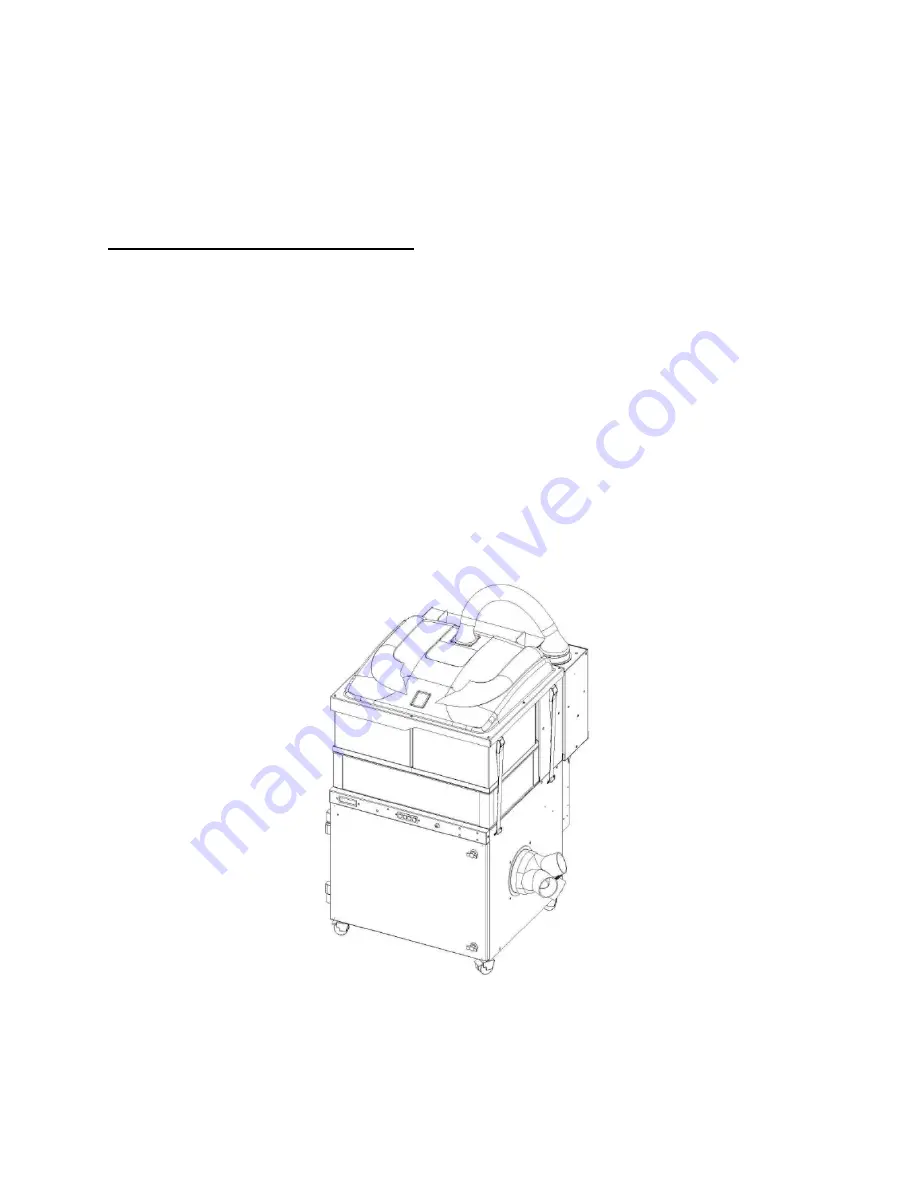
PHYSICAL SET-UP TO LASER 


! Important Note: The Calibration system will take all air resistance caused by 
the flex hose and laser into account and provide optimal performance. 

1.


Connect the 80 mm hoses onto the machine via the adapter that is provided with machine 

2.


Place the Filtrabox in the final position that it will be regularly used. This is important for 
Calibration as the Calibration system will take all the bends and flow restrictions of the flex hose 
into account and provide optimal performance.  

3.


Connect the mains power cord to an appropriate supply. 

4.


Go to the 

QUICK START INSTRUCTIONS

 on the next page to begin using your Filtrabox.  


Summary of Contents for EXPAND 3

Page 1: ...FILTRABOX EXPAND 3 USER MANUAL...

Page 2: ...2...

Page 3: ...c AIRFLOW SETTING pg 11 vi FILTER REPLACEMENT INSTRUCTIONS a WHEN TO REPLACE FILTERS pg 12 b HOW TO REPLACE FILTERS pg 13 vii BLOWER MODULE REPLACEMENTS pg 17 viii USER INTERFACE MODULE REPLACEMENT p...

Page 4: ...any module by fastening a few screws and snapping a single cable connection per module SPECIFICATIONS Expand 3 Voltage 240V Frequency Hz 50 60 Wattage kW 5 5 Blower Type 3x Brushless Length mm inches...

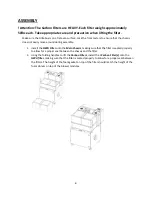
Page 5: ...when lifting the filter Remove all the packaging and place all of the parts on the floor Take inventory of the parts included with your kit i Expand 3 Machine Cylindrical Pre Filter Pre installed ii...

Page 6: ...assembly 1 Install the HEPA Filter onto the Main Chassis making sure that the filter is seated properly to allow for a proper seal between the chassis and the filter 2 Using the folding handles to li...

Page 7: ...e sides of the Lid Press the lever on the clamps if more strap length is required 5 Pull on the loose end of the strap to create a light tension on all four straps Once all four straps are taught furt...

Page 8: ...achine via the adapter that is provided with machine 2 Place the Filtrabox in the final position that it will be regularly used This is important for Calibration as the Calibration system will take al...

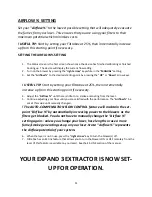
Page 9: ...2 Fill in the required fields and you will be sent an email message containing your AUTHENTICATION CODE 3 Turn your Filtrabox ON using the main power switch located in the back of the device Filtrabo...

Page 10: ...r is closed before performing the calibration process The EXPAND 3 has 3 blowers This is important to remember before calibrating your device 2 While on the OF BLOWERS screen select the number of blow...

Page 11: ...increase up from this starting point if necessary 4 Adjust the Airflow until there is little to no smoke emanating from the laser 5 Continue adjusting your flow until you are satisfied with the perfor...

Page 12: ...extractor is not generating enough airflow due to a filter blockage This should be also be indicated by a Check Filter warning on the user interface However I If the Check Filter warning is not active...

Page 13: ...Cylindrical Pre Filter Remove larger particles 2 HEPA Filter Removes finer particles 3 Carbon Filter Removes odor All three filters will need to be independently replaced at some point in time during...

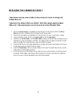
Page 14: ...se the filters to be inefficiently used causing frequent filter changes REPLACING THE CYLINDRICAL PRE FILTER Important Note The Pre Filter Retaining Bar must be in locked position while Filtrabox is i...

Page 15: ...oper seal between the chassis and the filter 6 Using the folding handles to lift the Carbon Filters re install the Carbon Filter onto the HEPA filter making sure that the filter is seated properly to...

Page 16: ...4 Install the new Carbon Filters onto the HEPA filter making sure that the filter is seated properly to allow for a proper seal between the filters The height of the foam gasket on the filter should m...

Page 17: ...PA filter off of the Main Chassis and set it aside 5 On the back of the Electronics Module there is a Blower Connector Access Panel See the Machine Diagram Remove the two screws on the panel Pull the...

Page 18: ...nd disconnecting a single ribbon cable Contact Filtrabox to order 1 Remove the two screws on the side of the User Interface Module Carefully pull the module out from the Chassis Be careful not to pull...

Page 19: ...ly set Airflow 2 Link On Off This mode uses the DB9 connection at the rear or the Filtrabox The blowers will be engaged at the previously set Airflow when laser requests it If feature is available on...

Page 20: ...tion Calibration will automatically initiate THIS MACHINE HAS 3 BLOWERS NEW APPLICATION CALIBRATION SETTING This will initiate the Calibration sequence Avoid doing this unnecessarily This should only...

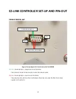
Page 21: ...ly Open Output from Laser Controller The controller connects these two pins to start the exhaust system Pins 8 9 Normally Open Input to Laser Controller The exhaust system will close the circuit betwe...

Page 22: ...em signal When creating the Check Filter signal the two wires for the signal should be shorted together using a relay This means that the exhaust system will not actively dump any current through thes...

Page 23: ...Filtrabox products and accessories please do contact us anytime It will be our pleasure to make fume extraction easier and more effective for any of your applications Please contact us through www fil...

Page 24: ...rvices PAT warrants that it will carry out the Services with reasonable care and skill If PAT is shown to be in breach of this warranty in respect of particular Services it shall at its option and cos...

Reviews: