
14
MACHINE PREPARATION
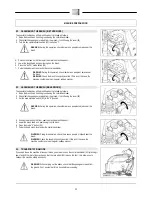
10. BATTERY MAINTENANCE AND DISPOSAL
For maintenance and recharging, respect the instructions provided by the battery manufacturer.
Particular attention must be paid when choosing the battery charger, if not supplied, since there are
different kinds according to the type and capacity of the battery.
When the battery reaches the end of its working life, it must be disconnected by expert, trained personnel
then removed from the battery compartment with the aid of suitable lifting devices. DEAD BATTERIES
ARE CLASSIFIED AS DANGEROUS WASTE AND MUST BE DELIVERED TO THE AUTHORISED
BODIES FOR CORRECT DISPOSAL.
11.
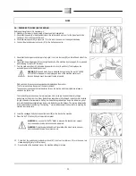
HANDLING - INSERTING BATTERIES
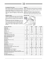
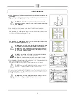
The batteries must be housed in the special compartment beneath the recovery tank and should be handled using
lifting equipment that is suitable in terms of both weight and coupling system. They must also satisfy the requirements
of Standard CEI 21-5. The dimensions of the battery compartment are: 353 mm x 333 mm x H250mm.
WARNING: Ensure that you comply with the accident prevention regulations in force
in the country where you work or with DIN EN 50272-3 and DIN EN 50110-1, before
any handling of the batteries.
WARNING: To prevent an accidental short circuit use insulated tools to connect the
batteries, and do not place or drop metal objects on the battery. Remove rings,
watches and any clothing with metal parts that may come into contact with the battery
terminals.
To insert the batteries into the compartment proceed as follows:
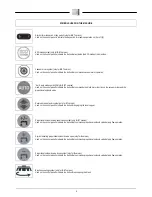
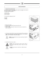
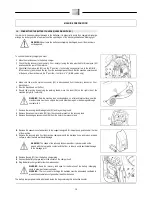
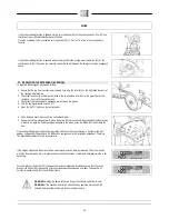
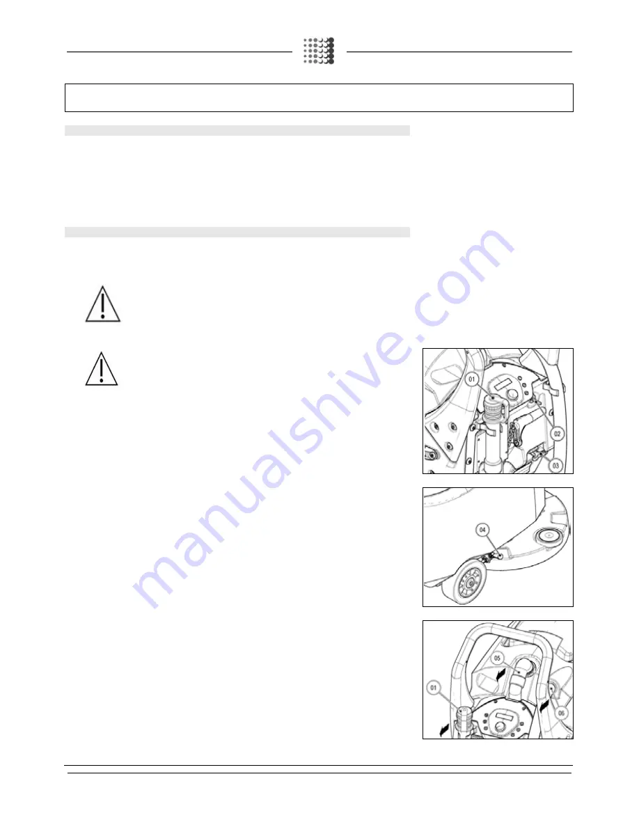
1.
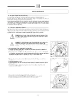
Check that the recovery tank is empty; if not, empty it using the tube provided for this purpose (01)
positioned at the rear of the machine.
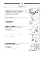
2.
Check that the main switch (02) is in the "0" position; if not turn the key a quarter turn to the left (for B-
BT version only), and remove the key from the instrument panel. Check that the machine's main switch
at the back of the machine is in the “0” position; if not, turn to “0” (for BB version only).
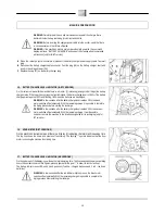
3.
Make sure the electric system connector (03) is disconnected from the battery connector; if not,
disconnect it.
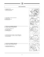
4.
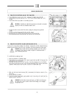
Rest the brush head on the floor.
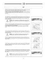
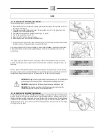
5.
Rest the squeegee on the floor, by moving the lever designed for this purpose, positioned on the rear
of the machine.
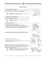
6.
Secure the machine by applying the parking brake, move the lever (04) on the right side of the
machine (only for BT versions).
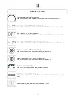
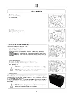
7.
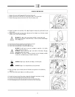
Remove the recovery tank drainage tube (01) and lay on the ground.
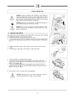
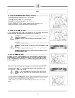
8.
Remove the vacuum motor tube (05) from the connector present on the recovery tank.
9.
Remove the squeegee vacuum hose (06) from the hole in the recovery tank.


