background image


27 


WORK


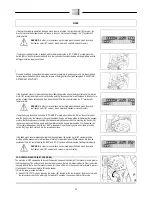
28.  REGULATING THE DETERGENT (BT VERSION) 

To regulate the detergent, proceed as follows: 
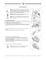
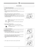
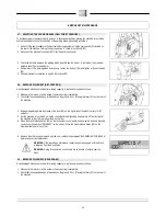
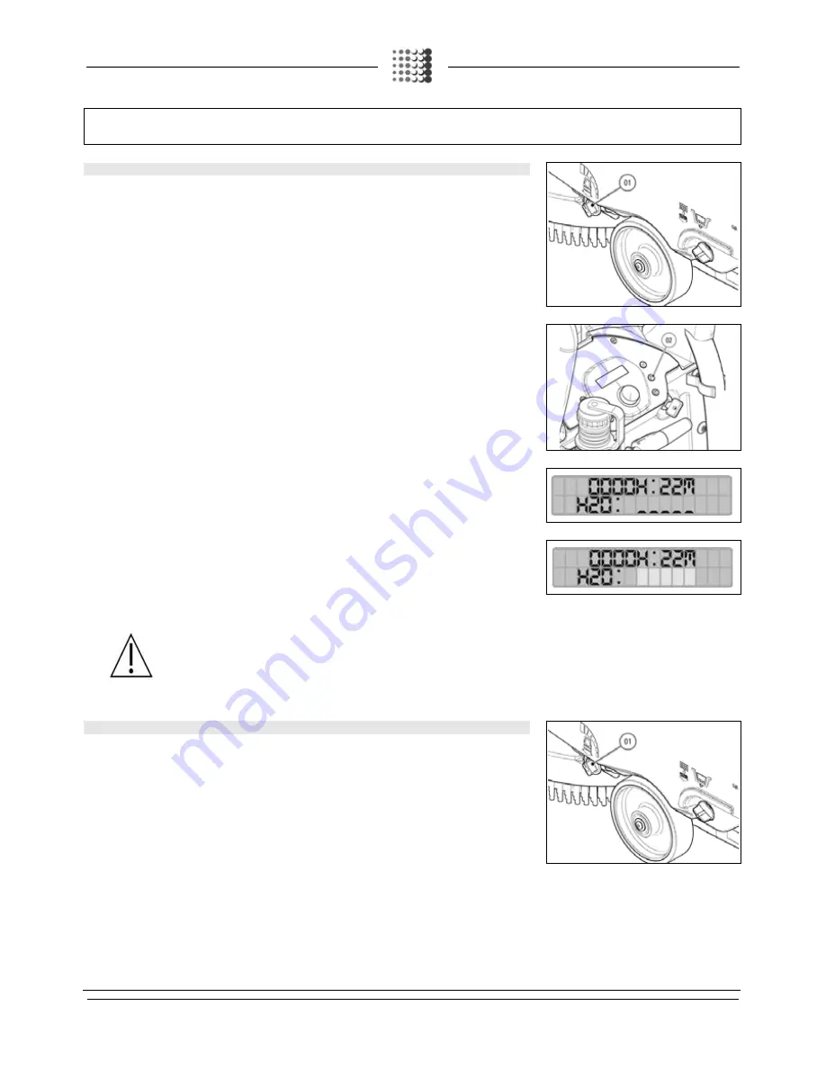
 

1.


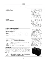
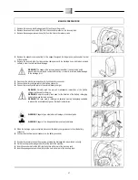
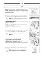
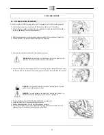
Ensure that the tap flow is at maximum capacity by turning the lever (01) on the right-hand rear part of 

the machine anticlockwise. 

2.


Check that the quantity of detergent solution in the solution tank is correct for the type of work to be 

carried out; if not, refill the solution tank. 

3.


Check that the brush head and squeegee are resting on the ground. 
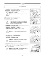
4.


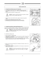
Turn the key operated main switch to “I”. 

5.


Press the “AUTO” button on the control panel. 

6.


Press the dead man's lever under the control handlebar. 


7.


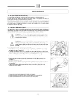
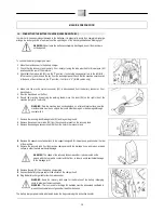
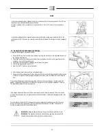
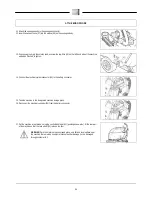
During the first fee meters of work, press the button (02) which controls the proportional solenoid valve 

to regulate the flow of detergent solution released onto the brush. 


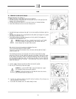
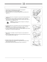
On pressing the button (02) on the control display, a horizontal line will appear, composed of five positions. 

As the button (02) is pressed, small rectangles will appear. There are five possible adjustments for the 

solenoid valve. 


If the display only shows the horizontal line, no detergent solution is being released. This mode is used 

when the floor is already wet or in general when the chemical action of water and detergent solution is not 

necessary. 


For each press of the button (02), the quantity of solution released will increase by one level. The quantity 

of solution released can be set to five different levels. Once the maximum level is reached (status shown in 

the right-hand display), pressing the button (02) again will return the flow to level 0 (no supply). 


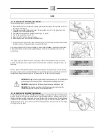
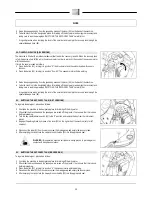
WARNING! Passing from one step to another is a continuous cycle - it is not possible to 

go back except by continuing to the end of the scale and starting again from zero. 

WARNING! Holding the button (02) down brings the solenoid valve flow to zero. 
WARNING!
 If the machine is switched off with the key operated main switch, the 

selected detergent flow will remain in the machine memory. 


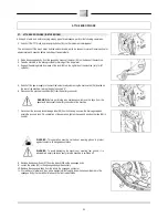
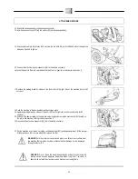
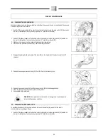
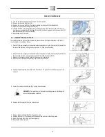
29.  REGULATING THE DETERGENT (BB VERSION) 

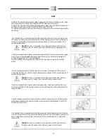
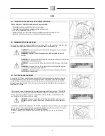
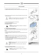
Firstly, fully open the tap outflow, by means of the lever (01) on the right-hand side at the back of the 

machine. During the first few meters check that the flow of detergent solution is sufficient to wet the floor; 

the flow of detergent solution is regulated by moving the lever (01). Turning the lever (01) anticlockwise 

increases the flow of detergent into the water system, while turning the lever (01) clockwise reduces the 

flow. Bear in mind that the correct amount of solution always depends on the nature of the floor, the degree 

of dirt and the forward speed. 


Summary of Contents for iMx 50B

Page 1: ...USE AND MAINTENANCE MANUAL iMx 50B iMx 50BT iMx 50BB ED 05 2013 EN ORIGINAL INSTRUCTIONS Doc 10042009 Ver AA...

Page 2: ...en book symbol with an i Indicates the need to consult the instruction manual Open book symbol Used to tell the operator to read the manual before using the machine Warning symbol Carefully read the s...

Page 3: ...ICATOR BB VERSIONS 19 18 FORWARD WORK SPEED BT VERSIONS 20 19 FORWARD WORK SPEED B BB VERSIONS 20 20 FILLING THE SOLUTION TANK 20 21 ASSEMBLING THE SQUEEGEE 21 22 ASSEMBLING THE BRUSH B BT VERSIONS 22...

Page 4: ...INE DIRECTION 43 51 REPLACING SQUEEGEE BODY RUBBERS 43 52 ADJUSTING THE SQUEEGEE INCLINATION 44 53 ADJUSTING THE SQUEEGEE HEIGHT 44 TROUBLESHOOTING 45 54 THE MACHINE DOES NOT START 45 55 INSUFFICIENT...

Page 5: ...ulties arise while using the machine If necessary remember that our customer assistance service organised in collaboration with our dealers is always available for advice or direct intervention Serial...

Page 6: ...al solenoid valve Reverse drive selector symbol only for BT version Used on the control panel to indicate the button for engaging the reverse gear Proportional solenoid valve open close symbol only fo...

Page 7: ...ersion Used on the control panel to indicate the button that commands the activation of the brush motor but not of the solenoid valve Symbol for vacuum motor switch ON VACUUM only for BB version Used...

Page 8: ...dicating the position of the recovery tank drainage tube Detergent flow control symbol Used on the machine to indicate the position of the lever used to control the flow of the detergent solution pres...

Page 9: ...collect dangerous powders Do not mix different types of detergent as this may produce harmful gases The machine is not suitable for cleaning carpets Do not place any liquid containers on the machine A...

Page 10: ...ke only for BT versions rotate the lever 1 on the right side of the machine anti clockwise 5 Use a chute to get the machine down from the pallet pushing it backwards Do not assemble the rear squeegee...

Page 11: ...ont components of the machine are identified as follows 1 Direction control knob 2 Fast water filler cap 3 Water filler cap detergent dispenser 4 Recovery tank lifting handle 4 SIDE COMPONENTS OF THE...

Page 12: ...nents are identified as follows 1 Level indicator for battery hour meter 2 ECO function button 3 Vacuum motor control button 4 AUTO function button 5 Proportional solenoid valve control button increas...

Page 13: ...motor Position 02 Switch in OFF VACUUM position deactivates the vacuum motor 4 Brush uncoupling switch WARNING From this point on in the document the positions of the main switch 02 will be identifie...

Page 14: ...tteries WARNING To prevent an accidental short circuit use insulated tools to connect the batteries and do not place or drop metal objects on the battery Remove rings watches and any clothing with met...

Page 15: ...g correctly WARNING Check that the characteristics of the battery that you are looking to use are appropriate for the type of work to be performed Check the battery charge and the condition of the con...

Page 16: ...witching on of the discharged batteries blinking light WARNING Never leave the batteries completely discharged even if the machine is not being used Check the battery charger is suitable for the batte...

Page 17: ...ly wired cable to the external battery charger WARNING Carefully read the use and maintenance instructions of the battery charger that is used for charging WARNING Keep the recovery tank open for the...

Page 18: ...ark the machine in an enclosed place on a flat and level surface near the machine there must be no objects that could either damage it or be damaged through contact with it 7 Remove the recovery tank...

Page 19: ...WARNING a few seconds after the battery charge level reaches 20 the brush motor switches off automatically With the remaining charge it is possible to complete the drying process before starting the...

Page 20: ...the instrument panel Check that the machine s main switch at the back of the machine is in the 0 position if not turn to 0 for BB version only 4 Engage the parking brake by means of the lever on the...

Page 21: ...ontact with the ground if not lower it 2 Turn the machine main switch 01 to the 0 position and remove the key from the instrument panel B BT versions Turn the machine main switch on the rear of the ma...

Page 22: ...eed as follows 1 Raise the brush head from the ground using the control handlebar 2 Check that the squeegee is raised from the ground if not lift using the lever 01 3 Set the main machine switch 02 to...

Page 23: ...ens are displayed on the monitor The first screen shows the name of the machine model The second screen shows the total operation time on the top line and the programme release is shown on the bottom...

Page 24: ...nd the O symbol will appear Once the scrubbing cycle is complete press the button 08 to go back over and dry the scrubbed surface If during the scrubbing operation the dead man s lever is released the...

Page 25: ...the main switch 01 is in the 0 position if not position it to 0 4 Connect the electric system connector 02 to the battery connector 5 Check that the detergent solution tap is fully open if not turn th...

Page 26: ...ress the dead man s lever under the control handlebar 7 During the first few metres of work press the button 02 which controls the proportional solenoid valve in order to increase the flow of detergen...

Page 27: ...emical action of water and detergent solution is not necessary For each press of the button 02 the quantity of solution released will increase by one level The quantity of solution released can be set...

Page 28: ...chine out of reverse function press the button 02 on the instrument control panel again 32 ECO DEVICE B BT VERSIONS By activating ECO mode using the dedicated button 09 the energy used by the machine...

Page 29: ...ton 06 on the control panel and the brush motor the vacuum motor and the solenoid valve will stop working immediately the vacuum motor will effectively cease to function after approximately fifteen se...

Page 30: ...el of the solution tank to empty the recovery tank through the special drainage hose 04 35 EMPTYING THE RECOVERY TANK B BT VERSIONS To regulate the detergent proceed as follows 1 First take the machin...

Page 31: ...key to position 0 6 Disconnect the electrical connector 05 from the battery connector WARNING Before performing any maintenance remove the keys from the panel and disconnect the battery connector of...

Page 32: ...of the lever 03 on the right side of the machine only for BT versions 20 Switch off the power supply to the machine s electrical system using the main switch 04 located on the rear of the machine tur...

Page 33: ...ove the keys from the panel and disconnect the battery connector of the machine 6 Disconnect the recovery tank drainage tube 5 from its housing unscrew the drainage cap and empty the recovery tank On...

Page 34: ...m connector 04 to the battery connector 15 Take the machine to the designated machine storage place 16 Disconnect the electrical connector 04 from the battery connector 17 Put the machine in rest mode...

Page 35: ...ns of the lever 03 on the right side of the machine only for BT versions 4 Loosen the solution tank filter cap 04 5 Rinse the cap filter carefully under running water 6 Remove any impurities present i...

Page 36: ...lows 1 Make sure the recovery tank is empty otherwise empty it completely 2 Check that the squeegee body is raised above the ground if not lift using the lever 01 on the rear of the machine 3 Engage t...

Page 37: ...ARNING During this operation check there are no people or objects near the brush 6 Rinse the brush carefully under running water 7 Read the paragraph ASSEMBLING THE BRUSH before reassembling all compo...

Page 38: ...et of water and then with a damp cloth thoroughly clean the rear rubber blade 09 of the squeegee body 12 Check the wear of the rear rubber blade 09 on the squeegee body if the edge of the rubber in co...

Page 39: ...ectrical connector 02 from the battery connector 4 Engage the parking brake by means of the lever 03 on the right side of the machine only for BT versions 5 Remove the squeegee vacuum hose 04 from the...

Page 40: ...BT versions 5 Remove the squeegee body vacuum hose 04 from the hole in the recovery tank WARNING This operation must be carried out using gloves to protect against contact with dangerous solutions 6...

Page 41: ...itch 01 located on the rear of the machine turning the key to position 0 valid for versions BB 1 Switch off the power supply to the machine s electrical system using the main switch 01 located on the...

Page 42: ...squeegee body is raised above the ground if not lift using the lever 01 on the rear of the machine 3 Engage the parking brake by means of the lever 02 on the right side of the machine only for BT vers...

Page 43: ...hine tends to veer to the right the knob must be turned clockwise whilst if the machine tends to veer to the left the know should be turned anticlockwise WARNING Directional operation of the machine s...

Page 44: ...QUEEGEE INCLINATION During working operation the rear rubber blade is slightly tilted backwards by about 5mm in a uniform way for its whole length If you need to increase the bend of the rubber in the...

Page 45: ...AINTENANCE Working with an over worn brush may cause damage to the floor 2 Use a different kind of brush to the one fitted as standard For cleaning floors where the dirt is particularly resistant we r...

Page 46: ...eparate the following materials and send them to the appropriate collection centres in accordance with the environmental hygiene regulations currently in force brushes felt electric and electronic par...

Page 47: ...ch can enter the gaps more easily Remember that when the bristles are worn and therefore too short they will become rigid and are no longer able to penetrate and clean deep down also because like with...

Page 48: ...for industrial environments EN 61000 6 3 Electromagnetic compatibility EMC Part 6 3 Generic standards Standard emission for residential commercial and light industrial environments EN 61000 3 2 Elect...

Reviews: