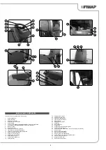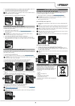
ASSEMBLING THE BRUSH (50BT VERSIONS)
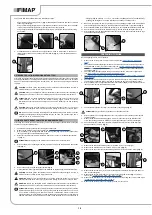
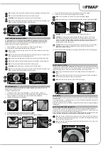
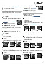
ASSEMBLING THE BRUSH (60BT VERSIONS)
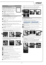
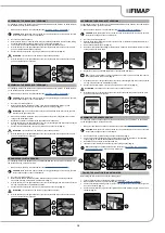
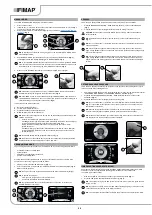
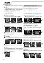
ASSEMBLING THE BRUSH (50BT VERSIONS)
ABRASIVE PAD (50BTO VERSIONS)
For packaging reasons, the brushes are supplied disassembled from the machine. To assemble them
on the brush head body, proceed as follows:
1. Make sure the machine is in a safe condition (see “
CAUTION
: these operations must be carried out using protective gloves to avoid any possible
contact with the edges or tips of metal objects.
2. Go to the front of the appliance.
3. With the brush head up, insert the brush in the plate housing underneath the brush head, turning
it until the three buttons engage with the notches on the plate itself (
Fig. 1
).
4. Turn until the pin is pushed towards the coupling spring and is locked into place.
5. Grip the handle (1) on the right-hand side of the recovery tank and turn the tank as far as it will
go, until it reaches the maintenance position.
6. Connect the electrical system connector (2) to the battery connector (3) (
Fig. 2
).
ATTENTION
: this process must be carried out by qualified personnel.
7. Grip the handle (1) on the right-hand side of the recovery tank and turn the tank as far as it will
go, until it reaches the work position.
For packaging reasons, the brushes are supplied disassembled from the machine. To assemble them
on the brush head body, proceed as follows:
1. Make sure the machine is in a safe condition (see “
CAUTION
: these operations must be carried out using protective gloves to avoid any possible
contact with the edges or tips of metal objects.
2. Go to the front of the appliance.
3. With the brush head in the raised position, press the brush-holder plate retainer (1) and
simultaneously rotate the brush in the direction shown in the image (
Fig. 1
).
ATTENTION
:
Fig. 1
shows the rotation direction of the left-hand brush, rotate in the opposite
direction for the right-hand brush.
4. When brush rotation is prevented, turn until the button on the brush is engaged in the coupling
spring on the brush-holder plate.
5. Repeat the operations completed for the right-hand front brush as well.
6. Grip the handle (2) on the right-hand side of the recovery tank (
Fig. 2
) and turn the tank as far as
it will go, until it reaches the maintenance position.
7. Connect the electrical system connector (3) to the battery connector (4) (
Fig. 3
).
ATTENTION
: this process must be carried out by qualified personnel.
8. Grip the handle (2) on the right-hand side of the recovery tank and turn the tank as far as it will
go, until it reaches the work position.
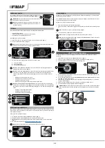
For packaging reasons, the brushes are supplied disassembled from the machine. To assemble them
on the brush head body, proceed as follows:
1. Make sure the machine is in a safe condition (see “
CAUTION
: these operations must be carried out using protective gloves to avoid any possible
contact with the edges or tips of metal objects.
2. Go to the front of the appliance.
3.
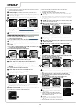
With the brush head raised from the floor, turn the knobs (1) that hold the left lateral carter (2) in
place anti-clockwise (
Fig. 1
).
4. Remove the left lateral carter (2) (
Fig. 2
).
5. Insert the brush into the tunnel (
Fig. 3
), taking care to make sure that the gearmotor's drive shaft
enters the slit in the brush itself.
For packaging reasons, the abrasive pad comes disassembled from the machine. To assemble it on
the brush head body, proceed as follows:
1. Make sure the machine is in a safe condition (see “
CAUTION
: these operations must be carried out using protective gloves to avoid any possible
contact with the edges or tips of metal objects.
2. Go to the front of the appliance.
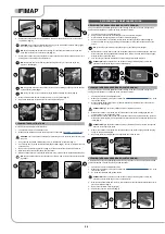
3. With the brush head in the raised position, slide the abrasive pad into the housing under the
brush head, pressing it until it is firmly attached to it (
Fig. 1
).
4. Grip the handle (1) on the right-hand side of the recovery tank (
Fig. 2
) and turn the tank as far as
it will go, until it reaches the maintenance position.
5. Connect the electrical system connector (2) to the battery connector (3) (
Fig. 3
).
ATTENTION
: this process must be carried out by qualified personnel.
6. Grip the handle (1) on the right-hand side of the recovery tank and turn the tank as far as it will
go, until it reaches the work position.
6. Repeat the previously described operations for the right-hand side as well.
N.B.
: In order to be installed correctly, the brushes must form an X when viewed from above in
the forward direction of movement (
Fig. 4
).
7. Grip the handle (3) on the right-hand side of the recovery tank (
Fig. 5
) and turn the tank as far as
it will go, until it reaches the maintenance position.
8. Connect the electrical system connector (4) to the battery connector (5) (
Fig. 6
).
ATTENTION
: this process must be carried out by qualified personnel.
9. Grip the handle (3) on the right-hand side of the recovery tank and turn the tank as far as it will
go, until it reaches the work position.
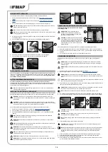
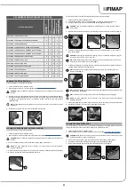
ASSEMBLING THE SQUEEGEE BODY
For packaging reasons, the squeegee body comes disassembled from the machine. To assemble it
on the squeegee support, proceed as follows:
1. Make sure the machine has been secured (see the section titled “
CAUTION
: these operations must be carried out using protective gloves to avoid any possible
contact with the edges or tips of metal objects.
2. Unscrew the knobs (1) in the squeegee body pre-assembly (
Fig. 1
).
3. First of all, insert the left-hand pin (2) on the squeegee body in the left slit (3) in the squeegee
support (
Fig. 2
), so that the bushing adheres to the walls of the slit.
4. Repeat the same operation for the right-hand pin.
5. Insert the vacuum tube (4) in the sleeve (5) in the squeegee body (
Fig. 3
).
NB
: the squeegee has already been adjusted, but refer to “
” if you need any information.
FILLING THE SOLUTION TANK WITH WATER
Before filling the solution tank, carry out the following steps:
1.
Take the machine to the usual place for filling the solution tank.
2. Make sure the machine is in a safe condition (see “
3. Check the solution tank drainage cap (1) (on the rear right-hand side of the machine) is tight. If it
isn't, turn it clockwise (
Fig. 1
).
4.
Check the water filter cap (2) (on the rear right-hand side of the machine) is tight. If it isn't, turn it
clockwise (
Fig. 2
).
15
1
2
2
1
1
3
3
2
2
3
3
1
1
1
2
1
3
2
4
3
6
5
2
1
1
2
2
1
3
2
3
1
1
2
3
1
2
5
3
6
4
5
4
Summary of Contents for MAXIMA 2017 PLUS
Page 2: ......
Page 36: ...36 NOTE ...
Page 37: ...37 NOTE ...
Page 38: ...38 NOTE ...
Page 39: ......


