background image

MANUAL MODE

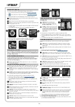
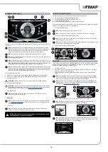
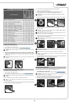
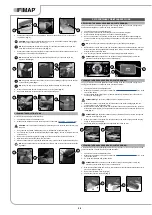
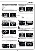
To activate the MANUAL-MODE program, proceed as follows:

1.  Sit on the driver’s seat.

2.  Insert the key (1) in the main switch on the control panel. Set the main switch to “I” by making a 

quarter turn of the key to the right (

 Fig. 1)

).

3.  Using the DS selector (2), select the working program you want; see “

DS SELECTOR (DRIVE 

SELECT)

” (

Fig. 2

).

NB

:


by selecting one of the three working programs on the DS selector, ECO-MODE will be 

automatically activated.

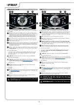
4.  Deactivate ECO-MODE by pressing the button (3) at the centre of the DS selector (

Fig. 2

); 

the display will move from ECO-MODE (

Fig. 2

) to MANUAL MODE (

Fig. 3

).

N.B.

: A grey ECO-MODE key means that economic mode is not active. A green ECO-MODE 

key means that economic mode is active. In addition, when ECO-MODE is not active, on the 

text indicator row (4) on the display, the word “MANUAL” will appear (

Fig. 2

).

5.  When you push the dead man's lever (5), the machine will begin to move (

Fig. 4

).

NB

:


if the button (3) is pressed when working in MANUAL MODE, the machine will shift to 

ECO-MODE, leaving the program in use at the time active (

Fig. 2

).

NB

:


if the “ZONE” button (6) is pressed when working in MANUAL MODE, the machine will 

shift to PROGRAM ZONE mode; as soon as button (6) is pressed, the screen enabling you to 

select the working zone will appear on the display (

Fig. 5

).

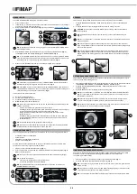
In manual mode, the visible buttons are:

A. 

Detergent solution adjustment.

B.  Vacuum motor performance level.

C.  Pressure exerted on the central brush head.

D.  Maximum forward movement speed level.

NB

: the four keys are always present, but can only be used depending on the working mode 

selected. In particular:

• 

Transfer: the visible button will be that of maximum speed.

• 

Scrubbing without drying: the buttons visible will be those of maximum speed, detergent 

solution adjustment and pressure exerted on the central brush head.

• 

Drying: the buttons visible will be those of maximum speed and vacuum motor 

performance level.

• 

Scrubbing with Drying: the buttons visible will be those of maximum speed, detergent 

solution adjustment, pressure exerted on the central brush head, and vacuum motor 

performance level.

NB

: the disabled buttons and the respective indicators are grey.

NB

: every time one of the enabled keys is pressed, the relative level is cyclically increased. 

Only the detergent solution adjustment can have a zero level.

PROGRAM ZONE MODE

The zone programs are programs saved in the machine memory. The following parameter levels:

• 

Pressure exerted on the brush head

• 

Forward speed

• 

Adjustment of the detergent solution flow

• 

Vacuum motor performance

are fixed, and have been created based on the type of environment in which you want to work.

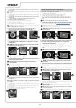
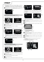
To select one of the zone programs, proceed as follows:

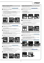
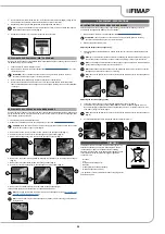
1.  From any screen, press the “ZONE” button (1) (

Fig. 1

).

2.  As soon as the button (1) is pressed, the “ZONE SELECTION” menu will be displayed (

Fig. 2

). 

Select one of the programs.


NB

: the name of the zone program selected is displayed in the 

text indicator (3) 

(

Fig. 1

).


NB

: to quit the zone program:

• 

From the zone program menu, select the “EXIT” key

• 

Enable and then disable the ECO-MODE key.


NB

: the light blue ZONE key shows that the selected zone is active. In this case, the 

ECO-MODE button is not active.

REVERSE

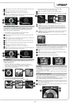
This machine is equipped with electronic traction control. To reverse, proceed as follows:

1.  Press the “REVERSE ACTIVATION - DEACTIVATION” button (1) on the control handlebars 

(

Fig. 1

).

2.  Press the dead man's lever (2) (

Fig. 2

) to start the machine moving in reverse.

CAUTION

: reverse speed is lower than forward speed, to comply with current health and 

safety standards.

NB

: to disable reverse movement, press the button (1) on the control handlebars again 

(

Fig. 1

).

NB

: as soon as the button (1) is pressed, the buzzer will sound to indicate that reverse mode 

has been activated.

NB

: if reverse gear is engaged with the squeegee in its working position, the machine will 

begin moving backwards as soon as the dead man's lever is pressed, and the squeegee body 

will rise to its idle position.

NB

: if reverse gear is engaged with the brush head in its working position, the machine will 

begin moving backwards as soon as the dead man's lever is pressed, and the brush head 

body will remain in its working position, but the solenoid valve will stop dispensing detergent 

solution.

EXTRA BRUSH HEAD PRESSURE

This machine is capable of increasing the pressure exerted upon the brushes during the work cycle. 

This can be done in the following manner:

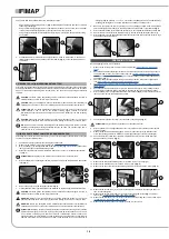
1. 

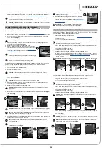
Check that the brush head body is in contact with the floor. If it isn't, use the DS selector to select 

“SCRUBBING WITH DRYING” or “SCRUBBING WITHOUT DRYING” (

Fig. 1

).

2.  Press the “EXTRA PRESSURE ACTIVATION - DEACTIVATION” button (1) on the control 

handlebars (

Fig. 2

).

3.  Press the dead man's lever (2) (

Fig. 3

) to start the working cycle.

NB

: as soon as the button (1) is pressed, the control display will show the “POWER” screen 

(

Fig. 4

). In the middle of the screen there is a graphic symbol (3) and a numeric symbol (4) 

that represent a countdown.

NB

: when the extra-pressure function is activated, the countdown starts. During this time, 

a pressure stronger than the standard pressure is exerted on the brush head body.

NB

: at the end of the countdown, you return to the working screen that was previously used 

and the pressure on the brush head goes back to standard.

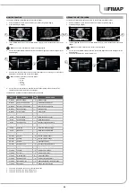
FIMAP SOLUTION SAVER SYSTEM (FSS)

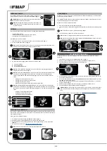
Upon request, the machine can be fitted with the FIMAP SOLUTION SAVER (FSS) system, which 

allows you to dose in a separated way the detergent with the water in the solution tank.

To activate it, proceed as follows.

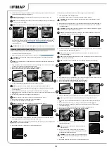
1.  With the machine on, press the menu button (1) on the working screen (

Fig. 1

).

2. 

Press the FSS system activation/deactivation button (2) (

Fig. 2

).

N.B.

: if the symbol (2) is grey the FSS system is not active, if the symbol (2) is green the FSS 

system is active.

NB

: to quit the menu screen, wait a short time without pressing anything, or else press on any 

point of the display (except one of the displayed buttons).

N.B.

: the FSS system activates when the electric pump in the machine's water system starts.

20

ECO mode

0000.00

100%

3

2

4

6

2

1

1

MANUAL

0000.00

100%

3

4

5

D

A

C

B

MANUAL

0000.00

100%

Warehouse

Canteen

Office

Reception

Exit

SELEZIONE ZONE

0000.00

100%

1

2

1

3

2

1

1

2

2

2

3

2

3

Back

0000.00

100%

POWER

0000.00

100%

1

4

Summary of Contents for MAXIMA 2017 PLUS

Page 1: ...ORIGINAL INSTRUCTIONS DOC 10076893 Ver AA 01 2018 PROFESSIONAL SCRUBBING MACHINES USE AND MAINTENANCE MANUAL MAXIMA 2017 PLUS ...

Page 2: ......

Page 3: ... battery charger 17 Solution tank drainage cap 18 Squeegee body 19 Squeegee body support 20 Squeegee vacuum tube 21 Water flow adjustment tap 22 Vacuum accessory support 23 Brush support 24 Squeegee body support 25 Headlights 26 Brush head body 27 Solution tank 28 Solution tank filler cap measuring inlet 29 Solution tank filler tube cap 30 Cover cap for FFF FIMAP FAST FILL quick coupling kit optio...

Page 4: ...0 PROGRAM ZONE MODE 20 REVERSE GEAR 20 EXTRA BRUSH HEAD PRESSURE 20 FIMAP SOLUTION SAVER SYSTEM FSS 20 FIMAP LONG RANGE FLR SYSTEM 21 VACUUM WAND KIT 21 SMART DRYING SYSTEM 21 HOUR METER 21 BATTERY CHARGE LEVEL INDICATOR 21 EMERGENCY SWITCH 22 TUTORIAL 22 SOLUTION TANK OVERFLOW 22 ALARM SCREEN 22 AT THE END OF THE WORK 22 RECOMMENDED MAINTENANCE OPERATIONS 23 EMPTYING THE RECOVERY TANK 23 CLEANING...

Page 5: ...t materials at a safe distance from the batteries Explosive gases are emitted during normal use Highly explosive hydrogen gas is generated while charging the batteries Keep the recovery tank unit in the maintenance position during the entire battery recharging cycle and only perform the procedure in well ventilated areas at a safe distance from any open flames Before charging make sure the electri...

Page 6: ...e been expressly authorised to do so This machine should not be used by persons including children with physical sensorial or mental impairments and by persons with little experience and or little knowledge of the machine itself The machine must only be used by authorised trained personnel Do not use the machine on surfaces with a slope greater than the one indicated on the serial number plate The...

Page 7: ...th shelving or scaffolding above all if there is a risk of objects falling from heights Do not place any liquid containers on the machine The machine must only be used under temperature conditions ranging from 0 C to 40 C When using detergents to clean the flooring always follow the instructions and respect the warnings indicated on the container labels Always use appropriate gloves and protective...

Page 8: ... allow metallic objects to fall upon the electrically powered components remove rings watches and or clothing with metallic parts that might come into contact with the electrically powered components Do not work underneath the raised machine without adequate fixed safety supports WARNING Read all the relevant instructions carefully before performing any maintenance repair operations If the machine...

Page 9: ...s of the site regarding battery removal If the machine needs to be tilted for maintenance procedures remove the batteries Have the machine checked by an authorised technical assistance centre every year When disposing of consumable materials observe the laws and regulations in force Once the machine has reached the end of its service life the materials contained within it must be disposed of in an...

Page 10: ...d in its special pouch close to the machine protected from liquids and anything else that could compromise its legibility When the machine is consigned to the customer an immediate check must be performed to ensure all the material mentioned in the shipping documents has been received and also to check the machine has not suffered damage during transportation If this is the case the carrier must a...

Page 11: ... rpm 2400 Brush head motor voltage nominal power V W 24 500 24 500 24 680 24 350 Maximum weight exerted on the brush head kg 36 Maximum possible gradient for uphill and downhill movement weight 2 10 Maximum slope during ascent and descent with the transport program weight 2 10 Maximum ambient temperature for machine operation C 40 Minimum ambient temperature for using the machine s scrubbing funct...

Page 12: ...olution tank after each use Moving brush hazard label Used on the machine to warn the operator not to place his her hands near the moving brush Label warning about the risk of crushed hands Indicates danger to hands due to crushing between two surfaces Position symbol for the solution tank drainage cap Applied to the back of the machine to identify the solution tank drainage cap Position symbol fo...

Page 13: ...pport are in the idle position raised from the pallet NB on the DS selector the symbol of the transport program 6 is green Fig 8 NB the grey symbols show working programs that are not active the green symbols show working programs that are active 14 Press the REVERSE ACTIVATION DEACTIVATION button 7 Fig 9 to engage the reverse gear 15 When you push the dead man s lever 8 Fig 10 the machine will be...

Page 14: ...ic weight and size WARNING the lifting hooks must not damage the blocks connectors or cables WARNING before inserting the batteries remember to cover the terminals with a little grease to protect them against external corrosion CONNECTING THE BATTERIES TO THE MACHINE SYSTEM The batteries should be connected so as to obtain a total voltage of 24V ATTENTION it is recommended that all installation an...

Page 15: ... Remove the left lateral carter 2 Fig 2 5 Insert the brush into the tunnel Fig 3 taking care to make sure that the gearmotor s drive shaft enters the slit in the brush itself For packaging reasons the abrasive pad comes disassembled from the machine To assemble it on the brush head body proceed as follows 1 Make sure the machine is in a safe condition see MACHINE SAFETY MEASURES CAUTION these oper...

Page 16: ...ts or solvents without this indication ATTENTION the dosing system is suitable for frequent maintenance cleaning acid or alkaline maintenance detergents can be used as long as they have pH values between 4 and 10 and do not contain oxidising agents chlorine or bromine formaldehyde mineral solvents The detergents used must be suitable for use with scrubbing machines Wash the circuit with water afte...

Page 17: ...d that the squeegee is drying correctly The appliance will now begin to work with full efficiency until the battery is flat or until the detergent solution has finished TRANSFER Selecting the program TRANSFER the control display screen will appear as shown in the figure NB with this working program both the brush head and squeegee support are in the idle position raised off the floor and the motor...

Page 18: ... is visible ATTENTION never switch off the machine while the brush head is in contact with the floor DRYING Selecting the program DRYING the control display screen will appear as shown in the figure NB with this working program the pressing of the dead man s lever only brings the squeegee to the work position in contact with the floor the brush head remains in the idle position raised from the flo...

Page 19: ...ch off the machine with the squeegee and or brush head in contact with the floor DS SELECTOR DRIVE SELECT The DS selector can be used to select one of the following working programs A Transfer movement of the machine without working B Scrubbing only using only the brushes in the brush head C Drying using the squeegee only D Scrubbing with Drying using both the brushes and the squeegee Pressing one...

Page 20: ...the EXIT key Enable and then disable the ECO MODE key NB the light blue ZONE key shows that the selected zone is active In this case the ECO MODE button is not active REVERSE This machine is equipped with electronic traction control To reverse proceed as follows 1 Press the REVERSE ACTIVATION DEACTIVATION button 1 on the control handlebars Fig 1 2 Press the dead man s lever 2 Fig 2 to start the ma...

Page 21: ...such as dust cigarette stubs paper etc CAUTION never collect gases explosive inflammable liquids or powders nor acids and solvents These include gasoline paint thinners and fuel oil which when mixed with the vacuum air can form explosive vapours or mixtures and also non diluted acids and solvents acetones aluminium and magnesium powders These substances may also corrode the materials used to const...

Page 22: ... A Fig 1 2 Bring the machine to the designated place for emptying the recovery tank 3 Switch off the machine by making a quarter turn to the left with the key 1 of the main switch Fig 2 4 Empty the recovery tank see EMPTYING THE RECOVERY TANK NB the machine will only resume correct operation after the next start up ALARM SCREEN When an error occurs the symbol 1 is displayed in the information fiel...

Page 23: ...o always wear goggles to avoid any risk of serious injury to your eyes N B before activating the optional tank cleaning kit check the level indicator 5 to see how much solution there is in the recovery tank Fig 5 6 Activate the solution jet by pressing the lever in the tank cleaning accessory Make sure the jet is pointing into the tank before pressing the lever NB to adjust the solution jet from t...

Page 24: ... clean the brush proceed as follows 1 Take the machine to the maintenance area 2 Using the DS selector on the control display select the transfer program 3 Press the brush uncoupling button 1 on the control display Fig 1 4 As soon as the button 1 is pressed confirm brush uncoupling screen will appear Fig 2 confirm the brush uncoupling by pressing the OK button 2 in the lower left hand area of the ...

Page 25: ...e lever in the tank cleaning accessory Make sure the jet is pointing into the tank before pressing the lever NB to adjust the solution jet from the tank cleaning accessory turn the knob 5 on the accessory itself Fig 5 N B to adjust the intensity of the solution jet from the tank cleaning accessory turn the knob 6 on the accessory itself Fig 6 N B to stop the solution jet use the lever 7 on the tan...

Page 26: ... 14 Repeat the operations in reverse order to reassemble all the parts To clean the recovery tank filters with the optional spray gun kit proceed as follows 1 Take the machine to the maintenance area 2 Using the DS selector on the control display select the transfer program CAUTION users are advised to always wear protective gloves to avoid the risk of serious injury to hands 3 Release the tank cl...

Page 27: ...o empty the solution tank 1 Take the machine to the maintenance area 2 Make sure the machine has been secured see the section titled SECURING THE MACHINE CAUTION users are advised to always wear protective gloves to avoid the risk of serious injury to hands 1 Fully open the tap outflow rotating the knob 1 in the direction of the arrow Fig 1 2 Unscrew the cap 2 of the solution tank drainage system ...

Page 28: ...firm brush uncoupling screen press the button 3 Fig 2 5 Replace the worn brush with the new one With the brush head in the raised position insert the brush in the plate housing underneath the brush head turning it until the three buttons engage with the notches on the plate itself 6 Turn until the pin is pushed towards the coupling spring and is locked into place ATTENTION these operations must be...

Page 29: ...semble all the parts NB before using the machine remember to adjust the squeegee body see ADJUSTING THE SQUEEGEE BODY RUBBER BLADES NB you are advised to replace both squeegee body blades in order to ensure good results when drying the floor ADJUSTMENT INTERVENTIONS ADJUSTING THE SQUEEGEE BODY RUBBER BLADES Careful adjustment of the squeegee body rubber blades guarantees better cleaning of the flo...

Page 30: ...OOR SCRUBBING MACHINES mod Maxima 2017 PLUS 50BT CB Maxima 2017 PLUS 60BT CB Maxima 2017 PLUS 50BTO CB Maxima 2017 PLUS 50BTS CB comply with the provisions of Directives 2006 42 EC Machinery Directive 2014 35 EC Low Voltage Directive 2014 30 EC Electromagnetic compatibility directive The person authorized to compile the technical file Mr Giancarlo Ruffo Via Invalidi del Lavoro 1 37059 Santa Maria ...

Page 31: ... NOT START There is a drive pedal fault Contact your nearest service centre NOT ENOUGH DETERGENT SOLUTION ON THE BRUSH The quantity of detergent solution in the water system is not sufficient for the work to be carried out Check that the amount of detergent solution present in the machine water system is sufficient for the work to be carried out Detergent solution filter obstructed Check the deter...

Page 32: ...e 4 Esci ZONE MANUAL ON OFF Programmazione Zone Zone 1 Zone 2 Zone 3 Zone 4 Esci ZONE MANUAL ON Monitor General Brush Pump Vacuum Traction Esci Valore 1 100 Valore 2 23 5 Valore 3 Valore 4 A V OFF ON Parametri General Brush Pump Vacuum Traction Esci Parametro 1 100 Parametro 2 List A Reset Menu principale COUNT Lingua Contaore Programmazione Zone Parametri Monitor Allarmi Esci Allarme 1 000 0000 0...

Page 33: ...R option 3 is selected all of the set hour meters stored in the machine will be displayed on the right hand side of the screen Fig 3 NB on the right hand side of the screen we can view the data relating to all of the set hour meters A Viewed B Key C Traction D Brush A Vacuuming 2 To reset the partial hour meter select the hour meter that you wish to reset 4 from the right hand side of the display ...

Page 34: ... appear on the display Fig 5 6 Select the program that you wish to change by selecting the name on the left hand side of the machine Fig 5 7 As soon as the zone program is selected the CHANGE ZONE PROGRAM Fig 6 8 When the button 6 on the right hand side of the screen is pressed Fig 6 the pop up for changing the program name appears Fig 7 NB as soon as the program name has been changed press the EN...

Page 35: ...CE 0000 00 100 OFFICE 0000 00 100 Reset Menu principale Lingua Contaore Programmazione Zone Parametri Monitor Allarmi Esci VISUALIZZATO TOTALE PARZIALE Chiave 0000 00 0000 00 Trazione 0000 00 0000 00 Spazzole 0000 00 0000 00 Aspirazione 0000 00 0000 00 Chiave Reset Menu principale Lingua Contaore Programmazione Zone Parametri Monitor Allarmi Esci VISUALIZZATO TOTALE PARZIALE Chiave 0000 00 0000 00...

Page 36: ...36 NOTE ...

Page 37: ...37 NOTE ...

Page 38: ...38 NOTE ...

Page 39: ......

Page 40: ...FIMAP spa Via Invalidi del Lavoro 1 37059 S Maria di Zevio Verona Italy Tel 39 045 6060411 Fax 39 045 6060417 E mail fimap fimap com www fimap com ...

Reviews: