background image

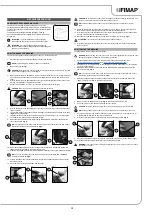
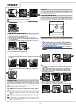
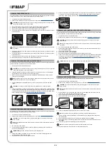
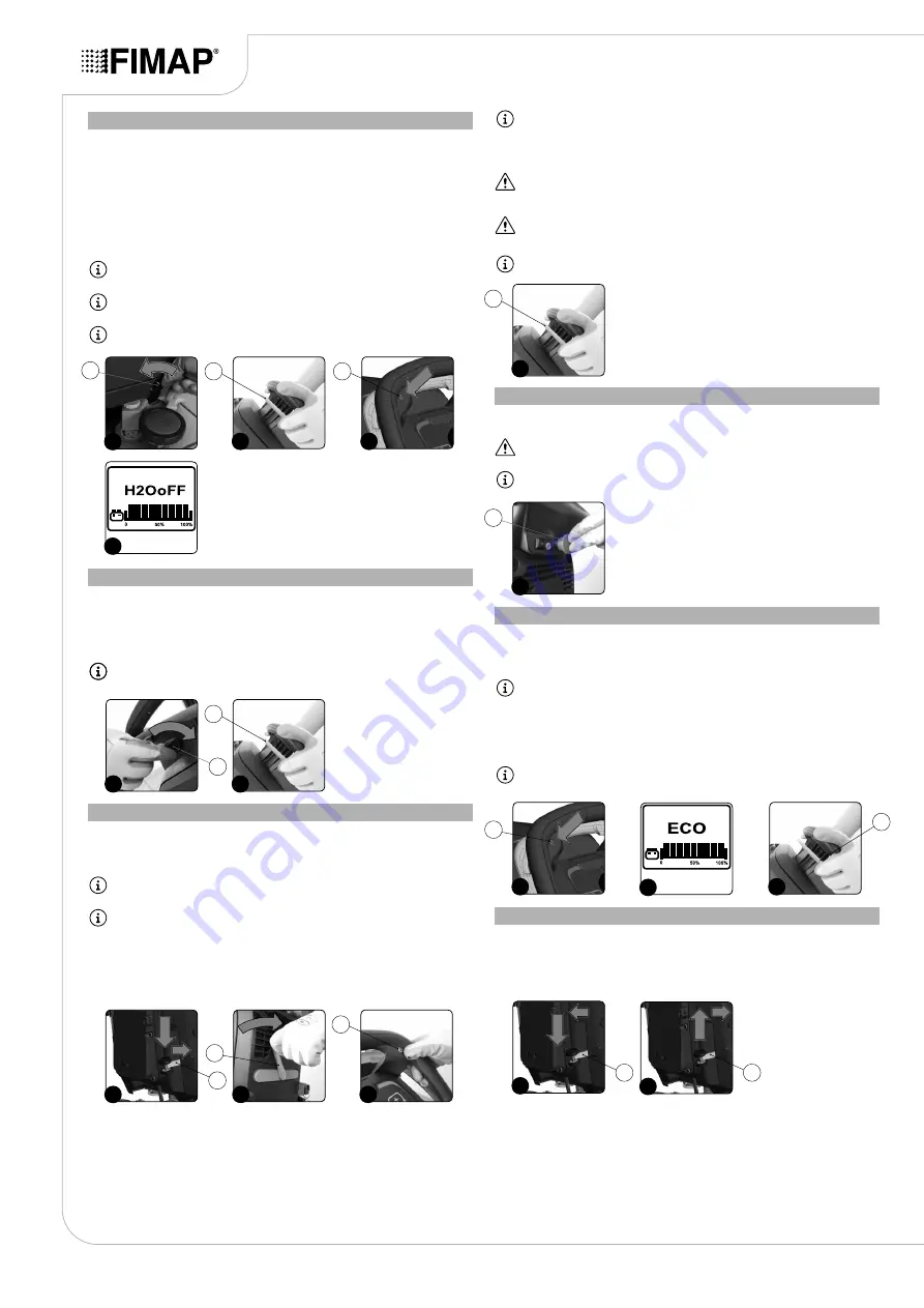
ADJUSTMENT OF THE DETERGENT SOLUTION FLOW

To adjust the flow of detergent solution during work, proceed as follows:

1.  Make sure the detergent solution tap is fully open, rotating the knob (1) in the direction of 

the arrow (

Fig.1

). As the knob is rotated, the flow of detergent in the machine water circuit is 

increased.

2.  By pushing the dead man's lever (2) the brush motor will start operating and the solenoid valve 

will distribute detergent solution to the brush (

Fig.2

).

3. 

During the first few meters check that the amount of solution is sufficient to wet the floor, but not 

excessive to exit the splash guard.

4.  If the amount of chemical that comes out is not suitable, it can be controlled via the knob (1) on 

the rear left-hand side of the machine (

Fig.1

).

NB

:


If you wish to stop the delivery of detergent solution completely when working, press the 

button (3) on the control handlebars (

Fig.3

).

NB

:


When the button (3) on the control display is pressed, the word “H2O STOP” will appear 

intermittently(

Fig.4

).

NB

:


To reactivate the delivery of the detergent solution, press the button (3) again (

Fig.3

).

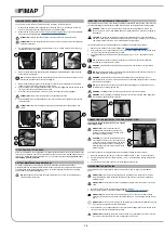
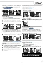
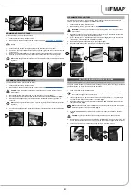
REGULATING THE FORWARD SPEED

This machine is equipped with electronic traction control. To adjust the forward speed during work, 

proceed as follows:

1.  Turn the main switch (1) to "I", making a quarter turn of the key in the direction of the arrow 

(

Fig.1

).

2.  Press the dead man's levers (2) underneath the control handlebars (

Fig.2

).

NB

:


The forward speed of the machine can be adjusted by varying the pressure on the dead 

man's lever (2). The more it is pressed, the more the forward speed will increase.

REVERSE

This machine is equipped with electronic traction control. To reverse, proceed as follows:

1.  Raise the brush head body and fully depress the "BRUSH HEAD CONTROL" pedal (1) at the 

rear of the machine (

Fig.1

).

NB

:


to lock the brush head in the raised position, depress the pedal (1) fully and then move it 

towards the right-hand side of the machine (

Fig.1

).

NB

:


if the brush head body is left in contact with the floor, the gearmotor will continue 

functioning but the solenoid valve will stop dispensing detergent solution on the brush.

2.  Raise the squeegee body and turn the squeegee control lever (2) in the direction of the arrow 

(

Fig.2

). The lever is located on the back of the machine.

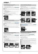
3.  Press the “REVERSE ACTIVATION - DEACTIVATION” button (3) on the control handlebars 

(

Fig.3

).

NB

:


As soon as the button (3) is pressed, the word “BACK” will appear on the control display 

(

Fig.4

).

4.  Activate the dead man's levers (5) on the handlebars (

Fig.4

) to start moving the machine in 

reverse mode.

WARNING

: the reverse speed is lower than the forward speed to comply with current health 

and safety standards. If the potentiometer is adjusted while reversing, the adjustment of the 

forward speed will be automatically changed.

WARNING

: it is impossible to reverse if the squeegee body touches the floor. In order to 

reverse, lift the squeegee body from the floor using the relevant lever on the back of the 

machine.

NB

: to disable reverse movement, press the button (4) on the control handlebars again.
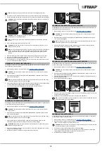
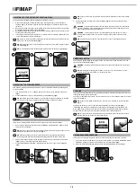
EMERGENCY BUTTON

This machine is equipped with an emergency switch. To activate it, just press the button (1) on the 

back of the control handlebars (

Fig.1

).

WARNING

: this control interrupts the electrical circuit between the batteries and the machine 

system.

NB

: after stopping and resolving the problem, turn the key to “0”, set the button (1) to the 

standard position and turn the key to “I” to resume the work.
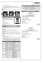
ECO MODE

This machine has an Eco-Mode function for reducing the noise generated by the vacuum motor, and for 

reducing the energy used by the machine.

To activate or deactivate this function, just press the button (1) on the instrument panel for at least 

three seconds (

Fig.1

).

N.B.

: When the Eco-Mode function is active, the word “ECO” will flash on the control display 

(

Fig.2

).

Just press the button (1) on the control panel to deactivate the "Eco-Mode" function (

Fig.1

).

If the dead man's lever (2) is released when performing a scrubbing with drying operation in Eco-

Mode (

Fig.3

), both the traction motor and the brush motor, along with the solenoid valve, will stop 

working, while the vacuum motor will continue to function until it is raised off the floor.

NB

:


To recommence work, simply press the dead man's lever (2) and the traction motor will 

start immediately; the brush motor; the solenoid valve.

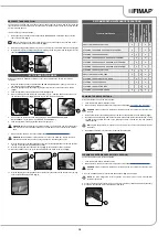
EXTRA BRUSH HEAD PRESSURE

This machine can increase the pressure exerted on the brush during the work cycle. To do this:

1.  Check that the brush head body is in contact with the ground; if not, detach the "BRUSH HEAD 

CONTROL" pedal (2) at the rear of the machine from the plate retainer (

Fig.1

).

2.  Raise the brush head pedal and engage it in the “EXTRA PRESSURE” position (

Fig.2

).

18

1

1

2

2

4

4

1

1

2

3

2

3

1

4

1

1

1

2

2

3

3

1

1

2

3

2

1

1

2

1

Summary of Contents for MAXIMA BASE BT 2017

Page 1: ...ORIGINAL INSTRUCTIONS DOC 10077109 Ver AA 01 2018 PROFESSIONAL SCRUBBING MACHINES USE AND MAINTENANCE MANUAL MAXIMA 2017 BASE BT ...

Page 2: ......

Page 3: ...On board battery charger optional 18 Solution tank drainage cap 19 Squeegee body 20 Squeegee body support 21 Vacuum tube 22 Water flow adjustment tap 23 Vacuum accessory support optional 24 Brush support 25 Squeegee body support optional 26 Headlights optional 27 Brush head body 28 Solution tank 29 Solution tank filler cap measuring inlet 30 Solution tank filler tube cap 31 Cover cap for FFF FIMAP...

Page 4: ...ON 19 CLEANING THE SQUEEGEE BODY 20 CLEANING THE BRUSH HEAD BRUSH 50BT VERSION 20 CLEANING THE BRUSH HEAD BRUSHES 60BT VERSIONS 20 CLEANING THE CYLINDRICAL BRUSHES 50BTS VERSIONS 20 CLEANING THE RECOVERY TANK 20 EMPTYING THE SOLUTION TANK 21 CLEANING THE WATER SYSTEM FILTER 21 CLEANING THE VACUUM TUBE 21 EXTRAORDINARY MAINTENANCE OPERATIONS 21 REPLACING THE BRUSH HEAD BRUSH 50BT VERSIONS 21 REPLAC...

Page 5: ...y charger socket Before charging make sure the electric cable that connects the battery charger to the mains is not damaged If it is don t use it contact technical assistance Do not disconnect the DC cable of the battery charger from the machine socket while the battery charger is operating This is necessary in order to avoid electric arcs forming To disconnect the battery charger when it is charg...

Page 6: ... impairments and by persons with little experience and or little knowledge of the machine itself The machine must only be used by authorised trained personnel Do not use the machine on surfaces with a slope greater than the one indicated on the serial number plate The machine is not suitable for cleaning rough or uneven floors Do not use the machine on slopes In the event of a fire use a powder ex...

Page 7: ...th shelving or scaffolding above all if there is a risk of objects falling from heights Do not place any liquid containers on the machine The machine must only be used under temperature conditions ranging from 0 C to 40 C When using detergents to clean the flooring always follow the instructions and respect the warnings indicated on the container labels Always use appropriate gloves and protective...

Page 8: ... allow metallic objects to fall upon the electrically powered components remove rings watches and or clothing with metallic parts that might come into contact with the electrically powered components Do not work underneath the raised machine without adequate fixed safety supports WARNING Read all the relevant instructions carefully before performing any maintenance repair operations If the machine...

Page 9: ...s of the site regarding battery removal If the machine needs to be tilted for maintenance procedures remove the batteries Have the machine checked by an authorised technical assistance centre every year When disposing of consumable materials observe the laws and regulations in force Once the machine has reached the end of its service life the materials contained within it must be disposed of in an...

Page 10: ...at could compromise its legibility When the machine is consigned to the customer an immediate check must be performed to ensure all the material mentioned in the shipping documents has been received and also to check the machine has not suffered damage during transportation If this is the case the carrier must ascertain the extent of the damage at once informing our customer service office It is o...

Page 11: ...d on the brush head kg 36 36 36 36 Maximum possible gradient for uphill and downhill movement weight 2 10 10 10 10 Maximum slope during ascent and descent with the transport program weight 2 10 10 10 10 Maximum ambient temperature for machine operation C 40 40 40 40 Minimum ambient temperature for using the machine s scrubbing functions C 0 0 0 0 Traction motor voltage rated power V W 24 150 24 15...

Page 12: ...ank filter daily care warning label Applied to the machine to remind the operator to clean the solution tank after each use Moving brush hazard label Used on the machine to warn the operator not to place his her hands near the moving brush Label warning about the risk of crushed hands Indicates danger to hands due to crushing between two surfaces Position symbol for the solution tank drainage cap ...

Page 13: ... underneath the control handlebars Fig 9 to start moving the machine in reverse 13 Use a ramp to bring the machine down from the pallet CAUTION do not fit the brush and the rear squeegee body before unloading the machine and avoid any violent jolts to the brush head and squeegee support NB the ramp gradient must not be such as to cause damage to the machine as it comes down 14 Switch off the machi...

Page 14: ...teries in the battery compartment are as follows 1 Make sure the machine is in a safe condition see MACHINE SAFETY MEASURES 2 Grip the handle 1 on the right hand side of the recovery tank Fig 1 and turn the tank as far as it will go until it reaches the maintenance position 3 House the batteries in the compartment positioning the poles and opposite each other Fig 2 NB for battery maintenance and d...

Page 15: ...e brush holder plate 5 Repeat the operations completed for the right hand front brush as well NB carefully read the use and maintenance instructions of the battery charger used 4 Go to the back of the machine and remove the cap 2 from the battery charger socket Fig 2 5 Connect the battery charger power cable connector 3 to the battery charger socket 4 Fig 3 CAUTION before connecting the batteries ...

Page 16: ...tenths of an hour a tenth of an hour corresponds to six minutes The flashing symbol indicates that the hour meter is counting the machine functioning time On the lower part of the display you can see the battery charge level When the batteries fitted in the machine are fully charged the line at the bottom consists of nine illuminated indicator bars As the batteries gradually run down the indicator...

Page 17: ...tinue working at maximum speed for a certain period of time and then switch off This ensures that all the liquid in the vacuum tube is eliminated NB when filling the solution tank it is good practice to empty the recovery tank using the special drainage tube SCRUBBING WITH DRYING To perform a scrubbing and drying program proceed as follows 1 Make all the checks listed in PREPARING TO WORK 2 Go to ...

Page 18: ...ACTIVATION DEACTIVATION button 3 on the control handlebars Fig 3 NB As soon as the button 3 is pressed the word BACK will appear on the control display Fig 4 4 Activate the dead man s levers 5 on the handlebars Fig 4 to start moving the machine in reverse mode WARNING the reverse speed is lower than the forward speed to comply with current health and safety standards If the potentiometer is adjust...

Page 19: ...t will go Fig 5 until it reaches the work position 10 Block the rotation of the prop 5 by pushing it towards the inside of the cover Fig 6 11 Grip the handle 4 on the right hand side of the recovery tank and turn the tank as far as it will go until it reaches the work position Fig 7 RECOMMENDED MAINTENANCE OPERATIONS DRAINING THE RECOVERY TANK Proceed as follows to empty the recovery tank 1 Take t...

Page 20: ...of the machine 4 Press the brush holder plate retainer 1 and simultaneously rotate the brush in the direction shown in the image Fig 1 ATTENTION Fig 1 shows the rotation direction of the left hand brush 5 When brush rotation is prevented turn until the button on the brush is disengaged from the coupling spring on the brush holder plate 6 Repeat the same operation for the right hand brush 7 Clean t...

Page 21: ...ke sure the machine is in a safe condition see MACHINE SAFETY MEASURES ATTENTION users are advised to always wear protective gloves to avoid the risk of serious injury to hands 3 Raise the squeegee body and turn the squeegee control lever 1 in the direction of the arrow Fig 1 The lever is located on the back of the machine 4 Grip the handle 2 on the left hand side of the recovery tank Fig 2 and tu...

Page 22: ...s drive shaft enters the slit in the brush itself 7 Repeat the previously described operations for the right hand side as well NB In order to be installed correctly the brushes must form an X when viewed from above in the forward direction of movement Fig 3 REPLACING THE SQUEEGEE BODY RUBBER BLADES Ensuring the good condition of the squeegee body rubber blades guarantees better floor cleaning and ...

Page 23: ...ad holder not only has anchor points but also a snap type central locking system in plastic that allows the abrasive floor pad to be perfectly centred and held without any risk of it becoming detached This type of pad holder is recommended above all for machines with more than one brush where the centring of the abrasive discs is difficult The undersigned manufacturer FIMAP spa Via Invalidi del La...

Page 24: ...MACHINE DOES NOT START There is a drive pedal fault Contact your nearest service centre NOT ENOUGH DETERGENT SOLUTION ON THE BRUSH The quantity of detergent solution in the water system is not sufficient for the work to be carried out Check that the amount of detergent solution present in the machine water system is sufficient for the work to be carried out Detergent solution filter obstructed Che...

Page 25: ...25 NOTE ...

Page 26: ...26 NOTE ...

Page 27: ......

Page 28: ...FIMAP spa Via Invalidi del Lavoro 1 37059 S Maria di Zevio Verona Italy Tel 39 045 6060411 Fax 39 045 6060417 E mail fimap fimap com www fimap com ...

Reviews: