

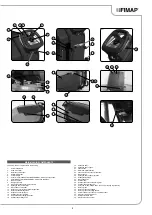
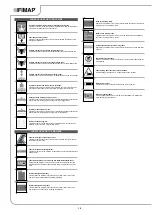
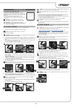


MACHINE SAFETY MEASURES
To ensure that work is carried out in the best safety conditions, proceed as follows:
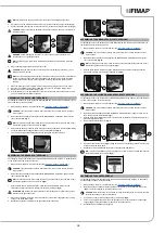
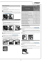
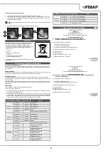
1. Make sure the electric brake is engaged, then rotate the lever (1) in the direction of the arrow.
The lever is located on the rear right-hand side of the machine (
Fig.1
).
2. Make sure the recovery tank is empty. If it isn't, empty it using the tube (2) on the rear left-hand
side of the machine (
Fig.2
ATTENTION
: the tanks should be emptied in the place used for draining dirty water.
ATTENTION
: the place designated for this operation must comply with current environmental
protection regulations.
3.
Switch off the machine by turning the main switch (3) to "0", making a quarter turn of the key in
the direction of the arrow (
Fig.3
).
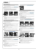
4. Raise the brush head body and fully depress the "BRUSH HEAD CONTROL" pedal (4) at the
rear of the machine (
Fig.4
).
NB
:
to lock the brush head in the raised position, depress the pedal (4) fully and then move it
towards the right-hand side of the machine (
Fig.4
).
5. Raise the squeegee body and turn the squeegee control lever (5) in the direction of the arrow
(
Fig.5
). The lever is located on the back of the machine.
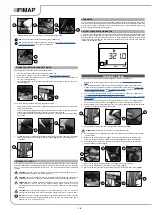
6. Grip the handle (6) on the right-hand side of the recovery tank (
Fig.6
) and turn the tank as far as
it will go, until it reaches the maintenance position.
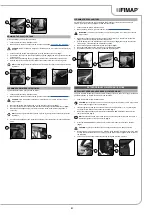
7. Disconnect the electrical system connector (7) from the battery connector (8) (
Fig.7
).
ATTENTION
: this process must be carried out by qualified personnel.
8. Grip the handle (6) on the right-hand side of the recovery tank and turn the tank until it reaches
the work position.
ATTENTION
: make sure the battery charger supply cable is disconnected from the mains
socket.
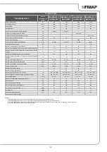
TYPE OF BATTERY TO BE USED
Power to the machine must be supplied by two sealed traction batteries with gas recombination or gel
technology. The batteries must meet the requirements laid out in the norms: CEI EN 60254-1:2005-12
(CEI 21-5) + CEI EN 60254-2:2008-06 (CEI 21-7). For the best work results,
we suggest the use of
two 12V MFP 112 Ah/C
5
batteries
.
BATTERY MAINTENANCE AND DISPOSAL
For battery maintenance and recharging, respect the instructions provided by the battery
manufacturer. When the batteries reach the end of their service life, they must be disconnected by
specialised and properly trained personnel, and must be subsequently removed from the battery
compartment using suitable lifting devices.
NB
: dead batteries are classified as dangerous waste and as such must be delivered to an
authorised body for disposal.
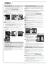
INSERTING THE BATTERIES IN THE MACHINE
The batteries must be housed in the relative compartment beneath the recovery tank. They should be
handled using lifting equipment that is suitable in terms of both the weight and the coupling system.
DANGER
: make sure you comply with the accident prevention regulations in force in the
country where you work or with DIN EN 50272-3 and DIN EN 50110-1, before any handling of
the batteries.
CAUTION
: to prevent an accidental short circuit use insulated tools to connect the batteries,
and do not place or drop metal objects on the battery. Remove rings, watches and any clothing
with metal parts that may come into contact with the battery terminals.
The various phases for inserting the batteries in the battery compartment are as follows:
1. Make sure the machine is in a safe condition (see “
”).
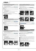
2. Grip the handle (1) on the right-hand side of the recovery tank (
Fig.1
) and turn the tank as far as
it will go, until it reaches the maintenance position.
3. House the batteries in the compartment, positioning the poles “+” and “-“ opposite each other
(
Fig.2
).
NB
: for battery maintenance and daily recharging, you must fully respect the indications
provided by the manufacturer or retailer.
WARNING
: all installation and maintenance operations must be carried out by specialised
personnel.
NB
: before installing the battery, clean the battery compartment. Check that the connectors on
the cables supplied are functioning correctly.
WARNING
: check that the characteristics of the battery that you are looking to use are
appropriate for the type of work to be performed. Check the battery charge and the condition of
the contacts on the battery.
NB
: you are advised to only lift and move the batteries with lifting and transportation means
suitable for the specific weight and size
WARNING
: the lifting hooks must not damage the blocks, connectors or cables.
WARNING
: before inserting the batteries, remember to cover the terminals with a little grease
to protect them against external corrosion.
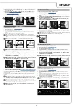
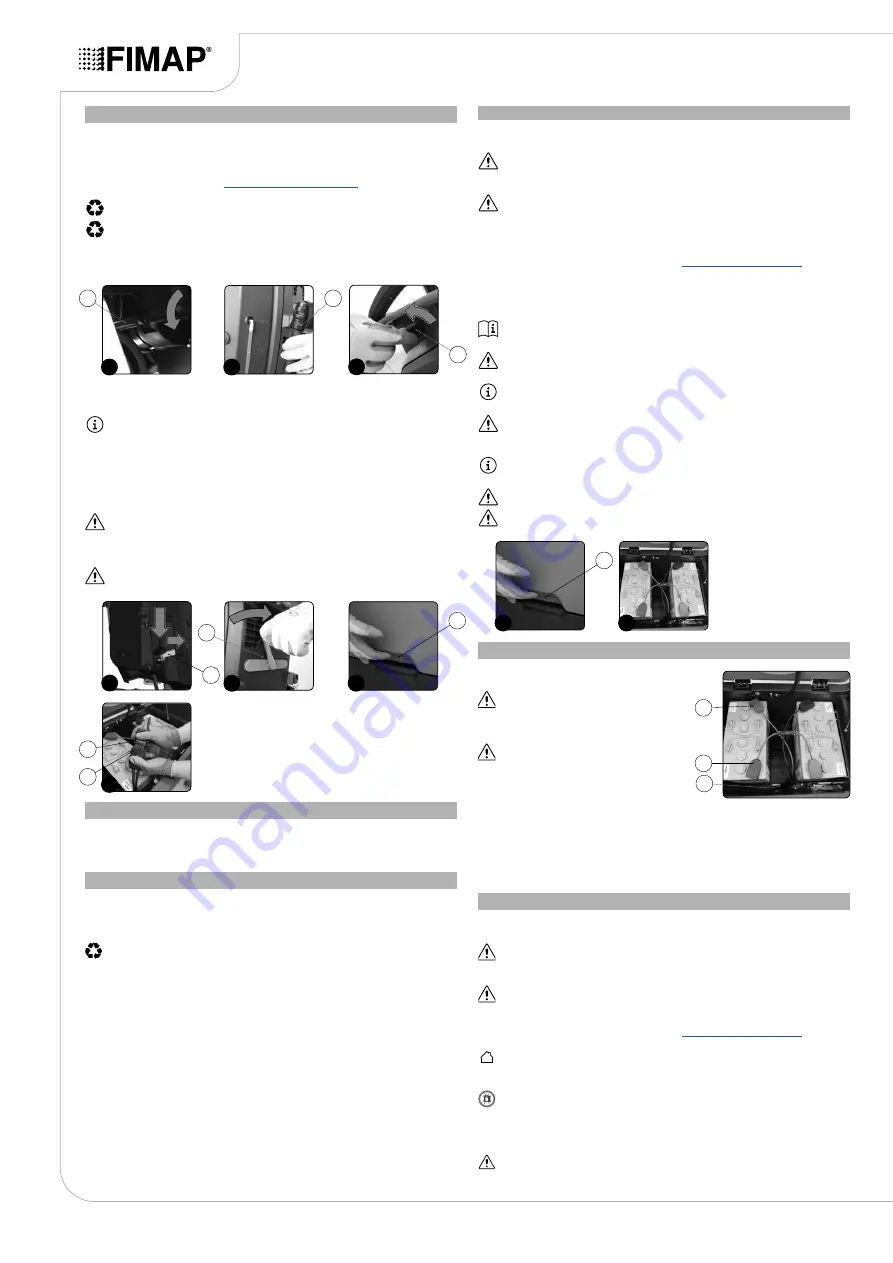
CONNECTING THE BATTERIES TO THE MACHINE SYSTEM
The batteries should be connected so as to obtain a
total voltage of 24V.
ATTENTION
: it is recommended that all
installation and maintenance operations be
carried out by expert personnel, trained at the
specialised assistance centre.
CAUTION
: to prevent an accidental short circuit
use insulated tools to connect the batteries, and
do not place or drop metal objects on the battery.
Remove rings, watches and any clothing with
metal parts that may come into contact with the
battery terminals.
The various phases for inserting the batteries in the battery compartment are as follows:
1.
Using the supplied jumper cable (1), connect the batteries to the "+" and "-" poles in sequence.
2. Connect the battery connector cable (2) to the “+” and “-“ poles to obtain a voltage of 24V at the
terminals.
3. Connect the electric system connector (3) to the battery connector (2).
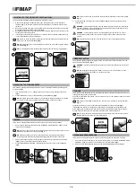
RECHARGING THE BATTERIES
The batteries must be charged prior to first use, and whenever they no longer provide sufficient
power.
ATTENTION
: to avoid any permanent damage to the batteries, it is essential to avoid their
complete discharge; begin recharging them within a few minutes of noting the "discharged
batteries" signal.
ATTENTION
: never leave the batteries completely discharged, even if the device is not being
used.
1. Bring the appliance to the area where the batteries are charged.
2. Make sure the machine is in a safe condition (see “
”).
ATTENTION
: park the machine in an enclosed place, on a flat and level surface; near the
machine there must be no objects that could either damage it, or be damaged through contact
with it.
ATTENTION
: the room used to recharge the batteries must be adequately ventilated to prevent
the accumulation of gases that leak from batteries.
3. Grip the handle (1) on the right-hand side of the recovery tank (
Fig.1
) and turn the tank as far as
it will go, until it reaches the maintenance position.
ATTENTION
: the following operations must be carried out by qualified personnel. An incorrect
connection of the connector may cause a malfunction of the device.
14
2
3
1
2
3
1
3
1
1
1
2
2
4
5
4
5
6
6
7
7
8


