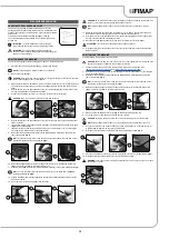
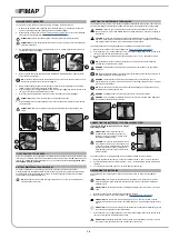
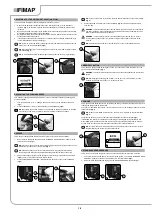
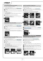


CLEANING THE SQUEEGEE BODY
The careful cleaning of the whole vacuum unit ensures better drying and cleaning of the floor as well as
a longer vacuum motor life. To clean the squeegee body, proceed as follows:
1. Take the machine to the maintenance area.
2. Make sure the machine has been secured (see the section titled “
”).
CAUTION
: these operations must be carried out using protective gloves to avoid any possible
contact with the edges or tips of metal objects.
3. Remove the vacuum tube (1) from the vacuum nozzle on the squeegee body (
Fig.1
).
4. Completely unscrew the knobs (2) in the squeegee body pre-assembly (
Fig.2
).
5. Remove the squeegee body from the slits in the squeegee connector (
Fig.3
).
6.
Thoroughly clean the vacuum chamber of the squeegee body, first with a jet of water and then
with a damp cloth.
NB
: the place designated for this operation must comply with current environmental protection
regulations.
7.
Thoroughly clean the rear rubber blade of the squeegee body, first with a jet of water and then
with a damp cloth.
8.
Thoroughly clean the front rubber blade of the squeegee body, first with a jet of water and then
with a damp cloth.
9.
Thoroughly clean the vacuum nozzle with a jet of water, and then with a damp cloth.
10. Repeat the operations in reverse order to reassemble all the parts.
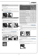
CLEANING THE BRUSH HEAD BRUSH (50BT VERSION)
Careful cleaning of the brush guarantees better cleaning of the floor, as well as a longer brush head
gearmotor lifespan. To clean the brush, proceed as follows:
1. Take the machine to the maintenance area.
CAUTION
: these operations must be carried out using protective gloves to avoid any possible
contact with the edges or tips of metal objects.
2. Insert the ignition key and switch on the machine. Turn the main switch (1) to “I” by rotating the
key a quarter turn in the direction shown by the arrow (
Fig.1
).
3. Raise the brush head body and fully depress the "BRUSH HEAD CONTROL" pedal (2) at the
rear of the machine (
Fig.2
).
NB
:
to lock the brush head in the raised position, depress the pedal (2) fully and then move it
towards the right-hand side of the machine (
Fig.2
).
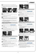
4. Press the “BRUSH UNCOUPLING” button (3) on the control panel for more than 3 seconds
(
Fig.3
).
CAUTION
: do not stand near the brush head body while the brush is being uncoupled.
5. Clean the brush under a stream of running water to remove any impurities from its bristles. Check
the wear status of the bristles and replace the brushes if they are excessively consumed (the bristle
protrusion must not be less than 10mm; this distance is indicated on the brush by the yellow band).
When replacing the brush, read "
REPLACING THE BRUSH HEAD BRUSH
".
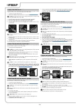
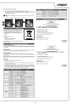
CLEANING THE BRUSH HEAD BRUSHES (60BT VERSIONS)
Careful cleaning of the brush guarantees better cleaning of the floor, as well as a longer brush head
gearmotor lifespan. To clean the brush, proceed as follows:
1. Take the machine to the maintenance area.
2. Make sure the machine has been secured (see the section titled “
”).
CAUTION
: users are advised to always wear protective gloves, to avoid the risk of serious
injury to hands.
NB
: the place designated for this operation must comply with current environmental protection
regulations.
3. Go to the front of the machine.
4. Press the brush-holder plate retainer (1) and simultaneously rotate the brush in the direction
shown in the image (
Fig.1
).
ATTENTION
:
Fig.1
shows the rotation direction of the left-hand brush.
5. When brush rotation is prevented, turn until the button on the brush is disengaged from the
coupling spring on the brush-holder plate.
6. Repeat the same operation for the right-hand brush.
7. Clean the brush under running water to remove any impurities from its bristles. Check the bristles
are not worn; in the event of excessive wear, replace the brush (the bristles should be at least
10mm long). When replacing the brush, read "
REPLACING THE BRUSH HEAD BRUSH
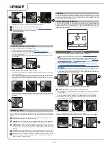
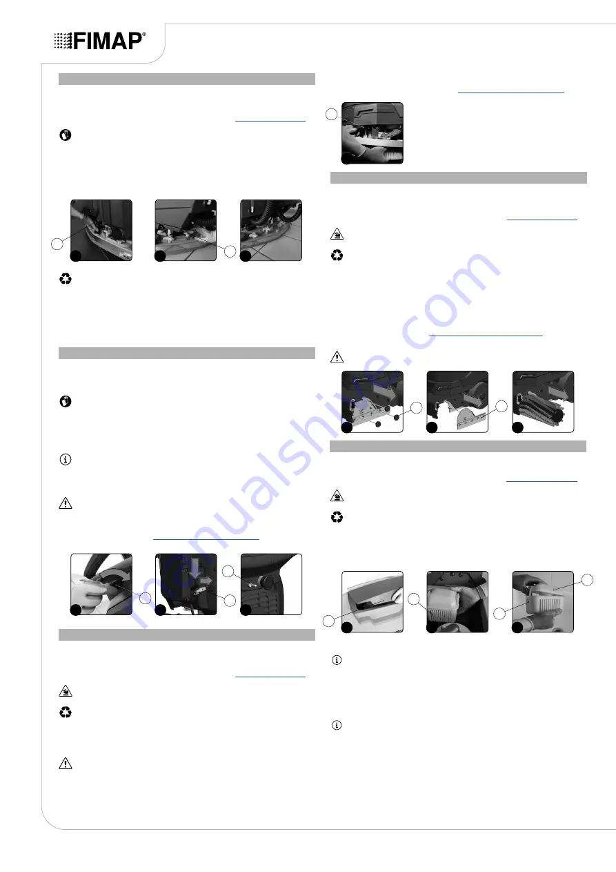
CLEANING THE CYLINDRICAL BRUSHES (50BTS VERSIONS)
Careful cleaning of the brush guarantees better cleaning of the floor, as well as a longer brush head
gearmotor lifespan. To clean the brush, proceed as follows:
1. Take the machine to the maintenance area.
2. Make sure the machine has been secured (see the section titled “
”).
CAUTION
: users are advised to always wear protective gloves, to avoid the risk of serious
injury to hands.
NB
: the place designated for this operation must comply with current environmental protection
regulations.
3. Go to the front left-hand side of the machine.
4.
With the brush head raised from the floor, turn the knobs (1) that hold the left lateral carter (2) in
place anti-clockwise (
Fig.1
).
5. Remove the left lateral carter (2) (
Fig.2
).
6. Extract the brush from the tunnel (
Fig.3
).
7. Repeat the previously described operations for the right-hand side as well.
8. Clean the brush under running water to remove any impurities from its bristles. Check the bristles
are not worn; in the event of excessive wear, replace the brush (the bristles should be at least
10mm long). Read the paragraph “
REPLACING THE CYLINDRICAL BRUSHES
” for info on how
to replace the brush.
ATTENTION:
Every time it is remove, swap the front brush with the rear brush, and vice versa.
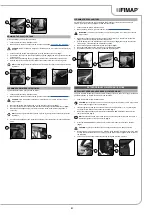
To clean the recovery tank (without the optional tank cleaning kit), proceed as follows:
1. Take the machine to the maintenance area.
2. Make sure the machine has been secured (see the section titled “
”).
CAUTION
: users are advised to always wear protective gloves, to avoid the risk of serious
injury to hands.
NB
: the place designated for this operation must comply with current environmental protection
regulations.
3. Grip the handle (1) on the left-hand side of the recovery tank (
Fig.1
) and turn the tank cover as
far as it will go, until it reaches the maintenance position.
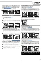
4.
Remove the dirty water basket/filter (2) from the support (
Fig.2
).
5.
Remove the basket cover (3) from the basket/filter (2) (
Fig.3
).
CLEANING THE RECOVERY TANK
6.
Clean the basket/filter (2) and the basket cover (3) under a jet of water.
NB
: use a spatula or brush to eliminate any dirt that is particularly difficult to remove.
7.
Use a dry cloth to dry the basket/filter (2) and the basket cover (3) and place them back inside
the recovery tank.
8.
Remove the filter protection cup (4), turning it in the direction of the arrow (
Fig.4
).
9.
Remove the vacuum motor filter (5), taking care not to lose the support tie (6) inside the recovery
tank (
Fig.5
).
10.
Rinse the cup (4) and filter (5) thoroughly under running water.
NB
: use a spatula to eliminate any dirt that is particularly difficult to remove.
11. Repeat the operations in reverse order to reassemble all the parts.
20
2
1
3
1
2
1
1
2
3
1
1
2
2
3
1
2
3
1
2
3
3
1
2
1
2


