


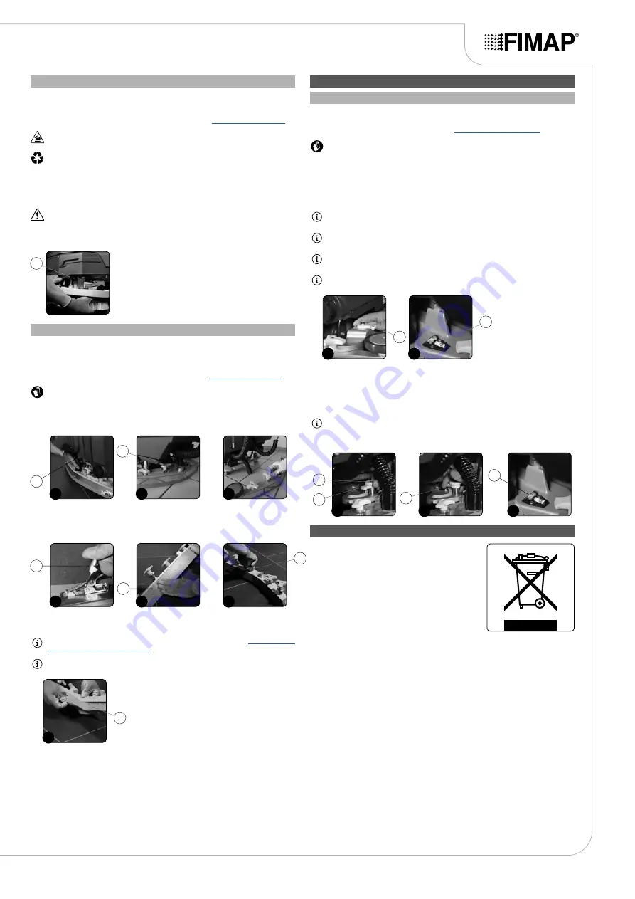
REPLACING THE BRUSH HEAD BRUSH (60BT VERSIONS)
The good condition of the brush guarantees better cleaning of the floor, as well as a longer brush head
gearmotor lifespan. To replace the brush, proceed as follows:
1. Take the machine to the maintenance area.
2. Make sure the machine has been secured (see the section titled “
CAUTION
: users are advised to always wear protective gloves, to avoid the risk of serious
injury to hands.
NB
: the place designated for this operation must comply with current environmental protection
regulations.
3. Go to the front of the machine.
4. Replace the worn brush with a new one.
5. Press the brush-holder plate retainer (1) and simultaneously rotate the brush in the direction
shown in the image (
Fig.1
).
ATTENTION
:
Fig.1
shows the rotation direction of the left-hand brush.
6. When brush rotation is prevented, turn until the button on the brush is disengaged from the
coupling spring on the brush-holder plate.
7. Repeat the same operation for the right-hand brush.
1
1
REPLACING THE SQUEEGEE BODY RUBBER BLADES
Ensuring the good condition of the squeegee body rubber blades guarantees better floor cleaning and
drying results, as well as a longer service life for the vacuum motor. To replace the squeegee body
rubber blades, proceed as follows:
1. Take the machine to the maintenance area.
2. Make sure the machine has been secured (see the section titled “
CAUTION
: these operations must be carried out using protective gloves to avoid any possible
contact with the edges or tips of metal objects.
3. Extract the vacuum hose (1) from the vacuum nozzle on the squeegee body (
Fig.1
).
4. Completely unscrew the knobs (2) in the squeegee body's pre-assembly (
Fig.2
).
5. Remove the squeegee body from the slits in the squeegee connector (
Fig.3
).
2
3
1
1
2
6. Remove the rear rubber blade compression plate, and release the stopper (3) at the rear of the
squeegee (
Fig.4
).
7. Remove the rear rubber blade (4) from the squeegee body (
Fig.5
).
8. Completely unscrew the knobs (5) in the squeegee body's pre-assembly (
Fig.6
).
5
6
4
3
4
5
9. Remove the front rubber blade (7) from the inside of the squeegee (
Fig.7
).
10. Repeat the operations in reverse order to reassemble all the parts.
NB
:
Before using the machine, remember to adjust the squeegee body (see “
”
).
NB
: you are advised to replace both squeegee body blades in order to ensure good results when
drying the floor.
7
6
ADJUSTMENT INTERVENTIONS
ADJUSTING THE SQUEEGEE BODY RUBBER BLADES
Careful adjustment of the squeegee body rubber blades guarantees better cleaning of the floor.
To adjust the squeegee body blades, proceed as follows:
1. Make sure the machine is in a safe condition (see “
ATTENTION
: these operations must be carried out using protective gloves to avoid any
possible contact with the edges or tips of metal objects.
2. Stand at the back of the machine.
Adjusting the height of the squeegee body:
3.
Adjust the height of the rubber blade in relation to the floor by loosening or tightening the knobs
(1) (
Fig.1
).
NB
: Figure 1 indicates the rotation direction for decreasing the distance between the squeegee
support and the floor. This distance can be increased by turning it in the opposite direction.
NB
: by decreasing the distance between the squeegee support and the floor, the rubber blades
present in the squeegee body move closer to the floor.
NB
: the right-hand and left-hand knobs must be rotated the same number of times, so that the
squeegee is parallel to the floor when it is working.
NB
: make sure the adjustment is correct by looking at the instrument (2) on the squeegee body
(
Fig.2
).
2
1
1
2
Adjusting the tilt of the squeegee body:
4.
Loosen the retainer knob (3) of the squeegee tilt adjustment knob (4) (
Fig.3
).
5.
To adjust the tilt of the squeegee body rubber blades in relation to the floor, tighten or loosen the
knob (5) (
Fig.4
) until the blades are bent outwards by about 30° in relation to the floor, in an even
manner along their entire length.
NB
: make sure the adjustment is correct by looking at the instrument (6) on the squeegee body
(
Fig.5
).
6.
Once the adjustment has been completed, tighten the retainer knob (3).
4
3
5
3
4
4
5
DISPOSAL
To dispose of the machine, take it to a demolition centre or an
authorised collection centre. Before scrapping the machine, it is
necessary to remove and separate out the following materials,
then send them to the appropriate collection centres in
accordance with the environmental hygiene regulations currently
in force:
• Brushes
• Felt
• Electric and electronic parts*
• Batteries
• Plastic parts (tanks and handlebars)
• Metal parts (levers and frame)
(*) In particular, contact your distributor when scrapping electric
and electronic parts.
19


