


AT THE END OF THE WORK
At the end of the work, and before carrying out any type of maintenance, perform the following
operations:
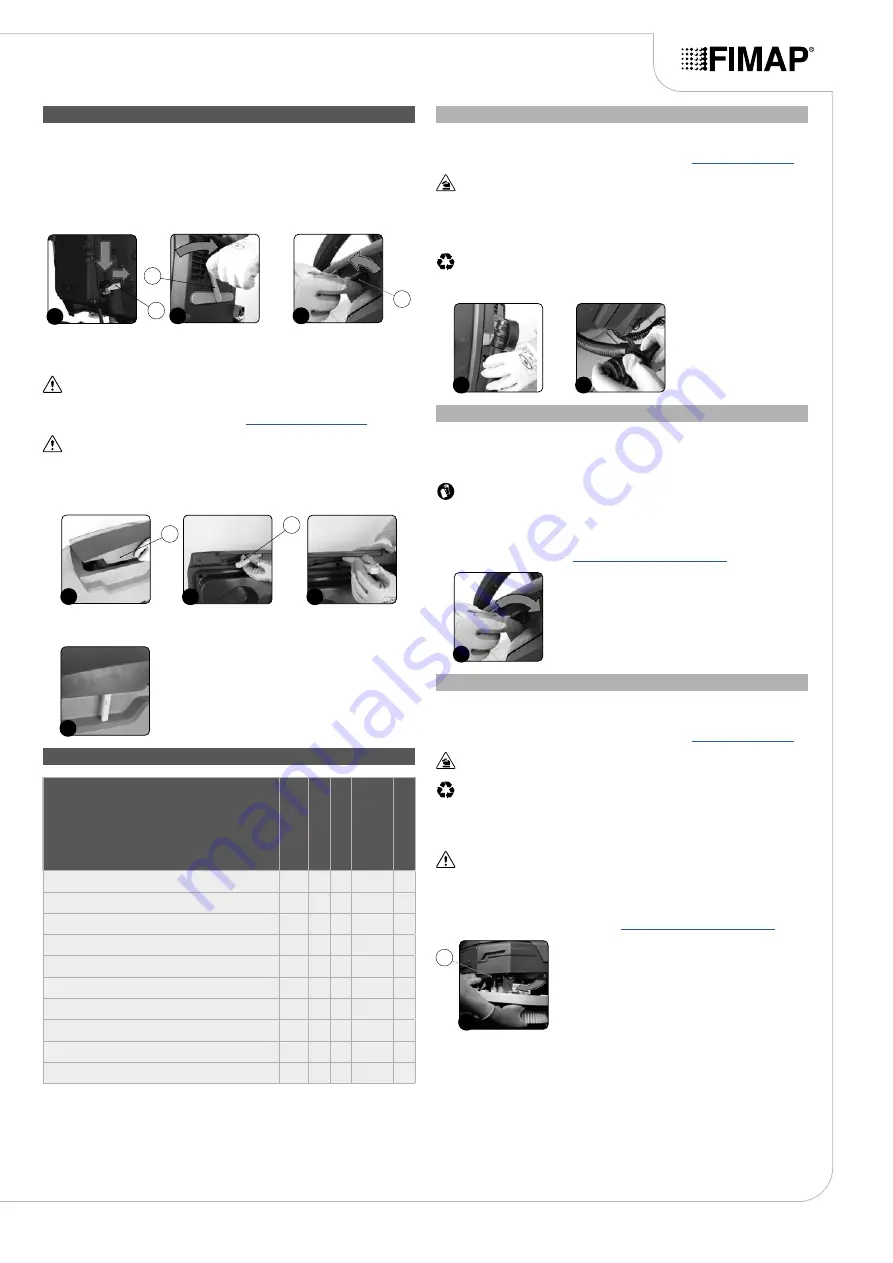
1. Raise the brush head body and detach the "BRUSH HEAD CONTROL" pedal (1) at the rear of
the machine from the plate retainer (
Fig.1
).
2.
Raise the squeegee body off the floor by means of the lever (2) on the back of the machine
(
Fig.2
).
3. Take the appliance to the dedicated dirty water drainage area.
4.
Switch off the machine by turning the main switch (3) to "0", making a quarter turn of the key in
the direction of the arrow (
Fig.3
). Remove the key from the instrument panel.
1
1
2
2
3
3
5. Carry out all the procedures listed in the paragraph “RECOMMENDED PERIODIC
MAINTENANCE” (in the column “AT THE END OF THE WORK”).
6. Take the appliance to the designated machine storage place.
ATTENTION
: park the machine in an enclosed place, on a flat surface, and at a safe distance
from any objects that could either damage it or be damaged due to contact with the machine
itself.
7. Make sure the machine is in a safe condition (see “
ATTENTION
: if the machine is left unused for more than one whole day, remove the brush
from the brush head body, and the squeegee body from the squeegee support.
8. Grip the handle (4) on the right-hand side of the recovery tank (
Fig.4
) and turn the tank as far as
it will go, until it reaches the maintenance position.
9. Grip the prop (5) and turn it as far as it will go (
Fig.5
), until it reaches the work position.
10. Block the rotation of the prop (5) by pushing it towards the inside of the cover (
Fig.6
).
5
5
6
4
4
11. Grip the handle (4) on the right-hand side of the recovery tank and turn the tank as far as it will go,
until it reaches the work position (
Fig.7
).
7
RECOMMENDED MAINTENANCE OPERATIONS
TYPE OF MAINTENANCE
AT THE END OF THE WORK
DAIL
Y
WEEKL
Y
BEFORE A
LONG
PERIOD OF NON- USE
TRANSPORT
DRAINING THE RECOVERY TANK
X
X
X
CLEANING THE SQUEEGEE BODY
X
X
X
CLEANING THE BRUSH HEAD BRUSH (VERSION 50E)
X
X
CLEANING THE BRUSH HEAD BRUSHES (60E VERSION)
X
X
CLEANING THE RECOVERY TANK
X
X
X
EMPTYING THE SOLUTION TANK
X
X
X
X
CLEANING THE WATER SYSTEM FILTER
X
X
CLEANING THE VACUUM TUBE
X
X
CLEANING THE SOLUTION TANK
X
X
CLEANING THE VACUUM WAND KIT
X
X
X
DRAINING THE RECOVERY TANK
Proceed as follows to empty the recovery tank:
1. Take the machine to the maintenance area.
2. Make sure the machine has been secured (see the section titled “
”).
CAUTION
: users are advised to always wear protective gloves, to avoid the risk of serious injury
to hands.
3. Release the recovery tank drainage tube (on the back of the machine) from the retainers (
Fig.1
).
4. Bend the end of the drainage tube in order to create a choke and prevent the content from coming
out (
Fig.2
), then position the tube on the discharge surface, unscrew the cap, and gradually
release the tube.
NB
: the place designated for this operation must comply with current environmental protection
regulations.
5. Repeat the operations in reverse order to reassemble all the parts.
2
1
CLEANING THE BRUSH HEAD BRUSH (VERSION 50E)
Careful cleaning of the brush guarantees better cleaning of the floor, as well as a longer brush head
gearmotor lifespan. To clean the brush, proceed as follows:
1. Take the machine to the maintenance area.
CAUTION
: these operations must be carried out using protective gloves to avoid any possible
contact with the edges or tips of metal objects.
2. Turn the brush anti-clockwise until it comes out of the seat of the brush-holder plate (
Fig.1
).
3. Clean the brush under a stream of running water to remove any impurities from its bristles. Check
the wear status of the bristles and replace the brushes if they are excessively consumed (the bristle
protrusion must not be less than 10mm; this distance is indicated on the brush by the yellow band).
When replacing the brush, read "
REPLACING THE BRUSH HEAD BRUSH
".
1
CLEANING THE BRUSH HEAD BRUSHES (VERSIONS 60E)
Careful cleaning of the brush guarantees better cleaning of the floor, as well as a longer brush head
gearmotor lifespan. To clean the brush, proceed as follows:
1. Take the machine to the maintenance area.
2. Make sure the machine has been secured (see the section titled “
”).
CAUTION
: users are advised to always wear protective gloves, to avoid the risk of serious
injury to hands.
N.B.
: the place designated for this operation must comply with current environmental
protection regulations.
3. Go to the front of the machine.
4. Press the brush-holder plate retainer (1) and simultaneously rotate the brush in the direction
shown in the image (
Fig.1
).
ATTENTION
:
Fig.1
shows the rotation direction of the left-hand brush.
5. When brush rotation is prevented, turn until the button on the brush is disengaged from the
coupling spring on the brush-holder plate.
6. Repeat the same operation for the right-hand brush.
7. Clean the brush under running water to remove any impurities from its bristles. Check the bristles
are not worn; in the event of excessive wear, replace the brush (the bristles should be at least
10mm long). When replacing the brush, read "
REPLACING THE BRUSH HEAD BRUSH
".
1
1
17


