CLEANING THE RECOVERY TANK
To clean the recovery tank (without the optional tank cleaning kit), proceed as follows:
1. Take the machine to the maintenance area.
2. Make sure the machine has been secured (see the section titled “
”).
CAUTION
: users are advised to always wear protective gloves, to avoid the risk of serious
injury to hands.
N.B.
: the place designated for this operation must comply with current environmental
protection regulations.
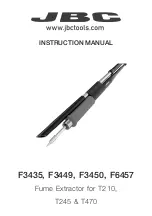
3. Grip the handle (1) on the left-hand side of the recovery tank (
Fig.1
) and turn the tank cover as
far as it will go, until it reaches the maintenance position.
4.
Remove the dirty water basket/filter (2) from the support (
Fig.2
).
5.
Remove the basket cover (3) from the basket/filter (2) (
Fig.3
).
2
3
1
1
2
2
3
6.
Clean the basket/filter (2) and the basket cover (3) under a jet of water.
NB
: use a spatula or brush to eliminate any dirt that is particularly difficult to remove.
7.
Use a dry cloth to dry the basket/filter (2) and the basket cover (3) and place them back inside
the recovery tank.
8.
Remove the filter protection cup (4), turning it in the direction of the arrow (
Fig.4
).
9.
Remove the vacuum motor filter (5), taking care not to lose the support tie (6) inside the recovery
tank (
Fig.5
).
10.
Rinse the cup (4) and filter (5) thoroughly under running water.
N.B.
: use a spatula to eliminate any dirt that is particularly difficult to remove.
11. Repeat the operations in reverse order to reassemble all the parts.
5
4
4
5
6
EMPTYING THE SOLUTION TANK
Proceed as follows to empty the solution tank:
1. Take the machine to the maintenance area.
2. Make sure the machine has been secured (see the section titled “
”).
CAUTION
: users are advised to always wear protective gloves, to avoid the risk of serious injury
to hands.
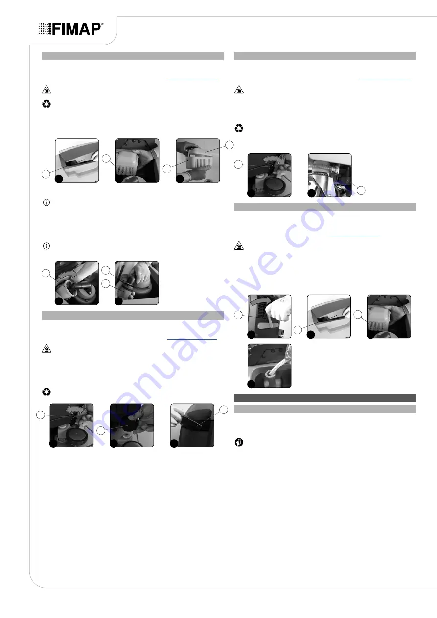
1.
Fully open the tap outflow, rotating the knob (1) in the direction of the arrow (
Fig.1
).
2. Unscrew the cap (2) of the solution tank drainage system (
Fig.2
); the cap is located at the rear
of the machine.
3.
Remove the cap/measuring device (3) (
Fig.3
), located on the left-hand side of the machine.
4.
With the solution tank empty, rinse the inside of the solution tank with a jet of running water.
N.B.
: the place designated for this operation must comply with current environmental protection
regulations.
2
3
1
1
2
3
CLEANING THE WATER SYSTEM FILTER
To clean the water system filter, proceed as follows:
1. Take the machine to the maintenance area.
2. Make sure the machine has been secured (see the section titled “
CAUTION
: users are advised to always wear protective gloves, to avoid the risk of serious
injury to hands.
3.
Block the tap outflow, rotating the knob (1) in the direction of the arrow (
Fig.1
).
4.
Go to the right-hand side of the machine and loosen the detergent solution filter cap (2) (
Fig.2
).
5.
Rinse the filter cartridge under a jet of water, and use a brush to eliminate any impurities, if
necessary.
N.B.
: the place designated for this operation must comply with current environmental
protection regulations.
6.
Once the filter cartridge is clean, repeat the operations in the reverse order to reassemble all the
parts.
2
1
1
2
CLEANING THE VACUUM TUBE
Careful cleaning of the vacuum tube guarantees better cleaning of the floor as well as a longer
vacuum motor life. Proceed as follows to clean the vacuum tube:
1. Take the machine to the maintenance area.
2. Make sure the machine has been secured (see “
ATTENTION
: users are advised to always wear protective gloves, to avoid the risk of serious
injury to hands.
3. Raise the squeegee body and turn the squeegee control lever (1) in the direction of the arrow
(
Fig.1
). The lever is located on the back of the machine.
4. Grip the handle (2) on the left-hand side of the recovery tank (
Fig.2
) and turn the tank cover as
far as it will go, until it reaches the maintenance position.
5.
Remove the dirty water basket/filter (3) from the support (
Fig.3
).
6.
Rinse the inside of the vacuum tube with a jet of running water (
Fig.4
).
7. Repeat the operations in reverse order to reassemble all the parts.
3
2
2
3
1
4
1
EXTRAORDINARY MAINTENANCE WORK
REPLACING THE BRUSH HEAD BRUSH (50BT VERSIONS)
The good condition of the brush guarantees better cleaning of the floor, as well as a longer brush head
gearmotor lifespan. To replace the brush, proceed as follows:
1. Take the machine to the maintenance area.
CAUTION
: these operations must be carried out using protective gloves to avoid any possible
contact with the edges or tips of metal objects.
2. Turn the brush anti-clockwise until it comes out of the seat of the brush-holder plate (
Fig.1
).
3. Replace the worn brush with a new one. With the brush head UP, insert the brush in the plate
housing underneath the brush head, turning it until the three buttons engage with the notches on
the plate itself.
4. Turn until the pin is pushed towards the coupling spring and is locked into place.
18