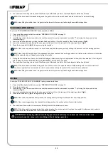
PAD (ORBITAL VERSION)” on page 18.
8. For scrubbing versions, check that the brush head body splashguard rubber blades are in good working condition. If they are worn, replace
them (see “REPLACING THE BRUSH HEAD SPLASHGUARDS (SCRUBBING VERSION)” on page 34.
9. For sweeping versions, check that the brush head body splashguard rubber blades are in good working condition. If they are worn, replace
them (see “REPLACING THE BRUSH HEAD SPLASHGUARDS (SWEEPING VERSION)” on page 34.
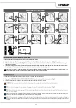
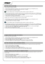
10. Check that the main switch is set to “0", turn the key (1) a quarter turn anticlockwise (
Fig.1
) . With the machine off, remove the key from the
instrument panel.
11. Grip the handle (2) and raise the recovery tank to the maintenance position (
Fig.2
).
CAUTION:
the following operations must be carried out by qualified personnel. An incorrect connection of the connector may cause a
malfunction of the device.
12. Connect the battery connector from the main machine system connector (
Fig.3
).
13. Rotate the recovery tank into the work position.
14. Move to the right rear part of the machine and check that the electro-brake in the traction gear motor is engaged; if not, turn the lever (3)
clockwise (
Fig. 4
).
15.
Move to the front of the machine and check that the water system filter cap (4) is closed, otherwise tighten it (
Fig.5
).
16. Move to the rear of the machine and check that the cap (5) of the solution tank drainage well is closed. If it isn't, close it (
Fig.6
).
17. Move to the front left-side of the machine and check that the water tap is fully open, move the water adjustment knob (6) in the direction
shown by the arrow (
Fig.7
).
18. Move to the rear of the machine a check that the cap of the recovery tank drainage tube (7) is closed. If it isn't, close it (
Fig.8
).
19. Make sure the vacuum hose (8) is correctly connected to the sleeve (9) in the squeegee body. If it isn't, connect it (
Fig.9
).
20. Grip the handle (10) and raise the recovery tank's lid to its maintenance position (
Fig.10
).
21.
Make sure the basket-filter (11) is correctly connected and is clean (
Fig.11
). If it isn't, clean it (see “CLEANING THE RECOVERY TANK
22. Make sure the anti-wave tray (12) is correctly connected and is clean (
Fig.12
). If it isn't, clean it (see “CLEANING THE RECOVERY TANK
STARTING WORK
Let's take the scrubbing with drying working programme as an example:
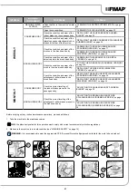
1. Carry out all the checks listed in the section “PREPARING TO WORK” on page 19.
2. Sit on the driver’s seat.
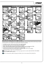
3. Insert the key (1) into the main switch on the control panel and move the main switch to position "I" by turning the key a quarter turn
clockwise (
Fig.1
).
N.B.:
As soon as the machine turns on, the control board will perform a diagnostics procedure, during which the red LED indicator (2) on
the control panel (
Fig.2
) will remain on.
N.B.:
If the control board's diagnostics procedure returns a positive outcome, the red LED indicator (2) on the control panel (
Fig.2
) will
turn off, and an acoustic signal will sound indicating that the work operations may be initiated.
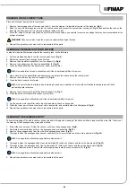
4. At switch-on, a number of screens appear in sequence on the control display.
20
1
2
5
6
7
1
4
2
9
6
8
7
5
3
4
3


