


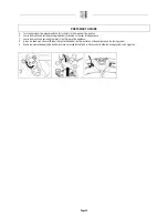

PREPARATION OF THE APPLIANCE
4.
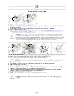
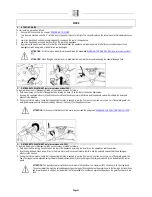
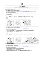
COMPONENT POSITIONING
The control panel components are identified as follows:
1.
Levers to activate brushes/traction (located beneath the grip)
2.
Water outlet adjustment switch (Versions with FSS)
3.
Detergent outlet adjustment switch (Versions with FSS)
4.
Main switch
5.
Control display
6.
Speed adjustment knob (BT versions)
7.
Brush uncoupling/eco-mode button
8.
Brush head unit lifting button
9.
Water/solution level tube
10.
Recovery tank drainage tube
11.
Hinge to close the tanks
12.
Compartment for battery charger / storage (depending on the
model)
13.
Squeegee lifting lever
14.
Solution filter
15.
Water outlet manual adjustment tap
16.
Recovery tank rotation handle
17.
Parking brake lever (only for BT versions)
18.
Vacuum system assembly rotation handle
19.
Upper storage compartment
20.
Solution tank inlet
5.
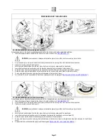
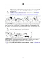
APPLIANCE SAFETY
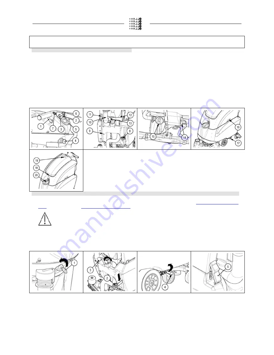
The steps to ensure machine safety, thereby allowing operations to be performed in full safety conditions, are the following:
1.
Check that the solution tank and recovery tank are empty, and empty them if necessary (see the paragraph, “
EMPTYING THE RECOVERY
TANK
” or read the paragraph, “
EMPTYING THE SOLUTION TANK
”).
WARNING: The tanks should be emptied in the place used for draining dirty water.
WARNING: The place this operation is carried out should comply with current environmental protection regulations.
2.
Check that the main switch is in the “0” position; if this is not the case, turn the key (1) by a quarter of a turn to the left. Remove the key from the
instrument panel.
3.
Check that the brush head unit is raised from the floor; if necessary turn the pedal (2) at the bottom of the device anticlockwise.
4.
Check that the squeegee body is raised from the floor; if necessary use the lever (3) at the rear of the device.
5.
For BT versions, check that the parking brake is on. If this is not the case, rotate the lever (4) in the sense shown by the picture
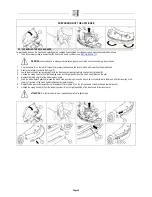
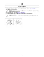
6.
Remove the recovery tank using the hinge (5).
7.
Grip the handle (6) on the left-hand side of the recovery tank.
8.
Lift the recovery tank until you reach the end position.
9.
Disconnect the battery connector (7) from the connector of the general system (8).
Page 10


