background image


INFORMAÇÕES PARA O 

USO E A LIMPEZA

3


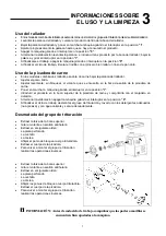
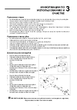
Uso do ralador


  Nos modelos combinados ralador - moedor de carne, desmonte o grupo de moedura antes de utilizar o 

ralador. 

  Levante a alavanca do ralador e introduza o produto na boca do ralador. 

  Abaixe a alavanca do ralador e rode o interruptor em 

“I”

  Prima progressivamente a alavanca até acabar o produto.   

  Para parar a máquina rode o interruptor em 

“0”

  No fim da laboração levante a alavanca e introduza outro produto na boca do ralador; abaixe novamente 

a alavanca e rode o interruptor em 

“I”

  No fim da laboração pare a máquina rodando o interruptor em 

“0”

  No fim do ciclo de trabalho limpe o cilindro ralando um pedaço de pão duro ou use o pincel em dotação. 


Uso do moedor de carne 

  Nos modelos combinados ralador - moedor de carne, abaixe a alavanca do ralador. 

  Aperte bem o manípulo da tubuladura. 

  Aperte ligeiramente, sem bloqueá-lo, o volante que se encontra na boca de saída do moedor de carne.  

  Ponha em movimento a máquina rodando o interruptor em 

“I”

  Introduza o produto na boca superior do moedor e prima-o com o almofariz em dotação. 

  Ao terminar a laboração rode o interruptor em 

“0”

  No fim do ciclo de trabalho desmonte o grupo de moedura e lave-o com detergentes apropriados (não 

agressiva em água quente e secar adequadamenteça.


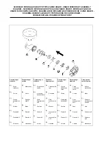
Desmontagem do grupo moedor 


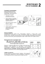
  Retire a tremonha da boca superior. 

  Rode em sentido anti-horário o volante. 

  Retire em sucessão: 

-


o disco furado 

-

 a 

faca 

-

 a 

cóclea 

  Rode os manípulos de bloqueio do corpo do 

moedor de carne e depois retire o corpo moedor. 

  Para montar o grupo moedor execute as 

operações em sucessão inversa. 


  INFORMAÇÕES: Antes de cada ciclo de trabalho verifique que as partes amovíveis estejam 

bem apertadas e fixas com a máquina. 


7

Summary of Contents for AB22/ATX

Page 1: ......

Page 2: ......

Page 3: ...aratteristiche tecniche Dimensioni d ingombro 2 INFORMAZIONI SULL INSTALLAZIONE Imballo e disimballo Zona d installazione Collegamento elettrico 4 4 5 6 6 6 3 INFORMAZIONI SULL USO E LA PULIZIA Uso della grattugia Uso del tritacarne Smontaggio gruppo macinazione ALLEGATI Schema di montaggio gruppo tritacarne unger Schema elettrico 7 7 7 ...

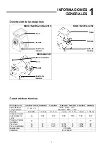
Page 4: ...niche Descrizioni Unità di misura TR22 RS TR22 RG TR32 RS TR22 TS TR32 TN AB22 AT Alimentazione di energia elettrica V Hz Ph 230V 50Hz 1Ph 230 400V 50Hz 3Ph Potenza kW HP 1 1 1 5 1 1 1 5 2 2 3 1 1 1 5 2 2 3 1 1 1 5 Produzione oraria tritacarne kg 300 300 500 300 500 300 Produzione oraria grattugia kg 40 Peso netto kg 32 33 5 43 53 31 42 52 39 Peso con imballo kg 38 39 5 49 59 37 48 58 45 Livello d...

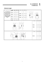
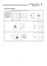
Page 5: ... C TR22 RS TR22 RG TR32 RS TR22 TS TR32 TN AB22 AT 420 420 420 420 420 450 570 570 570 570 570 700 700 700 700 700 700 720 TR22 RS TR22 RG TR32 RS 410 410 490 310 310 340 510 490 530 mm A B C TR22 TS TR32 TN 420 520 300 320 520 550 mm A B C AB22 AT 430 540 480 5 ...

Page 6: ...enti con atmosfera non esplosiva In ogni modo l installazione deve essere eseguita tenendo conto anche delle leggi vigenti in materia di sicurezza sul lavoro Collegamento elettrico PERICOLO ATTENZIONE Il collegamento elettrico alla rete di alimentazione deve essere eseguito da personale specializzato Collegamento Collegamento monofase trifase 230V 1Ph 230 400V 3Ph Accertarsi della perfetta efficie...

Page 7: ...la bocca d uscita del tritacarne Avviare la macchina ruotando l interruttore sulla posizione I Introdurre il prodotto all interno della bocca superiore del tritacarne e comprimere quest ultimo con il pestello in dotazione Al termine della lavorazione ruotare l interruttore sulla posizione 0 Alla fine del ciclo di lavoro smontare il gruppo macinazione e lavarlo con detergenti idonei non agressivi i...

Page 8: ......

Page 9: ...ON Machine description Specifications Overall dimensions 2 INSTALLATION Packing and unpacking Installation area Electric connection 4 4 5 6 6 6 3 OPERATION AND CLEANING Using the grater Using the mincer Dismantling the mincing set ANNEXES Unger mincing set assembly diagram Electrical wiring diagram 7 7 7 ...

Page 10: ...nel Specifications Description Unit of measure TR22 RS TR22 RG TR32 RS TR22 TS TR32 TN AB22 AT Electric power input V Hz Ph 230V 50Hz 1Ph 230 400V 50Hz 3Ph Power kW HP 1 1 1 5 1 1 1 5 2 2 3 1 1 1 5 2 2 3 1 1 1 5 Mincer output kg 300 300 500 300 500 300 Grater output kg 40 Net weight kg 32 33 5 43 53 31 42 52 39 Packaged weight kg 38 39 5 49 59 37 48 58 45 Noise 70 dB A Installation On the table 4 ...

Page 11: ... TR22 RS TR22 RG TR32 RS TR22 TS TR32 TN AB22 AT 420 420 420 420 420 450 570 570 570 570 570 700 700 700 700 700 700 720 TR22 RS TR22 RG TR32 RS 410 410 490 310 310 340 510 490 530 mm A B C TR22 TS TR32 TN 420 520 300 320 520 550 mm A B C AB22 AT 430 540 480 5 ...

Page 12: ... environments In any case installation should be carried out by taking into account any applicable industrial safety regulations in force Electric connection DANGER CAUTION Electric connection to the power mains should be executed by skilled engineers Single phase Three phase connection connection 230V 1Ph 230 400V 3Ph Check for the perfect effeciency of the plant grounding system Make sure that t...

Page 13: ...th of the mincer without blocking Start up the machine by turning the switch on position I Place the product inside the upper mincer mouth and press it down using the pestle supplied At the end of the work session turn the switch on position 0 At the end of the work cycle remove the mincer set and wash using suitable detergents not aggressive in hot water and dry properly Dismantling the mincer se...

Page 14: ......

Page 15: ...techniques Dimensions d encombrement 2 INFORMATIONS SUR L INSTALLATION Emballage et déballage Zone d installation Branchement électrique 4 4 5 6 6 6 3 INFORMATIONS SUR L UTILISATION ET LE NETTOYAGE Utilisation de la râpe Utilisation du hache viande Démontage groupe hachoir ANNEXES Schéma de montage groupe hache viande unger Schéma électrique 7 7 7 ...

Page 16: ...niques Descriptions Unité de mesure TR22 RS TR 22RG TR32 RS TR22 TS TR32 TN AB22 AT Alimentationen énergie V Hz Ph 230V 50Hz 1Ph 230 400V 50Hz 3Ph Puissance kW HP 1 1 1 5 1 1 1 5 2 2 3 1 1 1 5 2 2 3 1 1 1 5 Productionparheure duhache viande kg 300 300 500 300 500 300 Productionparheure delarâpe kg 40 Poidsnet kg 32 33 5 43 53 31 42 52 39 Poidsavec emballage kg 38 39 5 49 59 37 48 58 45 Niveaudebru...

Page 17: ...A B C TR22 RS TR22 RG TR32 RS TR22 TS TR32 TN AB22 AT 420 420 420 420 420 450 570 570 570 570 570 700 700 700 700 700 700 720 TR22 RS TR22 RG TR32 RS 410 410 490 310 310 340 510 490 530 mm A B C TR22 TS TR32 TN 420 520 300 320 520 550 mm A B C AB22 AT 430 540 480 5 ...

Page 18: ...mosphère explosive En tous cas l installation doit être exécutée en tenant compte aussi des lois en vigueur en matière de sécurité dans le lieu de travail Branchement électrique DANGER ATTENTION Le branchement électrique sur le réseau d alimentation doit être exécuté par du personnel spécialisé Branchement Branchement monophasé triphasé 230V 1Ph 230 400V 3Ph S assurer que l installation de mise à ...

Page 19: ...nde Mettre en route la machine en tournant l interrupteur sur la position I Introduire le produit à l intérieur de l ouverture supérieure du hache viande et comprimer ce dernier avec le poussoir en dotation Au terme du traitement arrêter la machine en tournant l interrupteur sur la position 0 A la fin du cycle de traitement démonter le groupe hachoir et le laver avec des détergents adéquats pas ag...

Page 20: ......

Page 21: ...reibung der Maschinen Technische Eigenschaften Abmessungen 2 AUFSTELLUNG Verpackung und Auspacken Aufstellbereich Elektrischer Anschluss 4 4 5 6 6 6 3 GEBRAUCH UND REINIGUNG Bedienung der Reibe Bedienung des Fleischwolfes Ausbau der Mahlgruppe ANLAGEN Ungersystem Fleischwolfgruppen Montageplan Schaltplan 7 7 7 ...

Page 22: ...chreibung Maßeinheit TR22 RS TR22 RG TR32 RS TR22 TS TR32 TN AB22 AT Stromversorgung V Hz Ph 230V 50Hz 1Ph 230 400V 50Hz 3Ph Leistung kW HP 1 1 1 5 1 1 1 5 2 2 3 1 1 1 5 2 2 3 1 1 1 5 Stundenleistung de Hackfleiscmaschine kg 300 300 500 300 500 300 Stundenleistung des Reibeisens kg 40 Nettogewicht kg 32 33 5 43 53 31 42 52 39 Gewicht mit Verpackung kg 38 39 5 49 59 37 48 58 45 Lärmpegel 70 dB A Au...

Page 23: ...2 RS TR22 RG TR32 RS TR22 TS TR32 TN AB22 AT 420 420 420 420 420 450 570 570 570 570 570 700 700 700 700 700 700 720 TR22 RS TR22 RG TR32 RS 410 410 490 310 310 340 510 490 530 mm A B C TR22 TS TR32 TN 420 520 300 320 520 550 mm A B C AB22 AT 430 540 480 5 ...

Page 24: ...lgen Das Aufstellen muss in jedem Fall auch unter Berücksichtigung der auf dem Gebiet der Sicherheit am Arbeitsplatz geltenden Gesetze erfolgen Elektrischer Anschluss GEFAHR ACHTUNG Der elektrische Anschluss an das Versorgungsnetz muss von Fachpersonal ausgeführt werden Einphasenanschluss Dreiphasenanschluss 230V 1Ph 230 400V 3Ph Volle Funktionstüchtigkeit der Erdungsvorrichtung der Anlage sichers...

Page 25: ...tellung I zum Starten der Maschine Geben Sie das Produkt in die obere Einfüllöffnung des Fleischwolfes und drücken Sie dieses unter Verwendung des mitgelieferten Stößels zusammen Am Ende des Arbeitsganges drehen Sie den Schalter zur Stellung 0 Am Ende des Arbeitszyklus bauen Sie die Mahlgruppe aus und waschen diese mit geeigneten Spülmitteln nicht aggressiv in warmem Wasser und richting zu trockne...

Page 26: ......

Page 27: ...erísticas técnicas Dimensiones totales 2 INFORMACIONES SOBRE LA INSTALACIÓN Embalaje y desembalaje Zona de instalación Conexión eléctrica 4 4 5 6 6 6 3 INFORMACIONES SOBRE EL USO Y LA LIMPIEZA Uso del rallador Uso de la picadora de carne Desmontado del grupo de trituración ANEXOS Esquema de montaje grupo picadora de carne unger Esquema electrico 7 7 7 ...

Page 28: ...ripciones Unidaddemedida TR22 RS TR22 RG TR32 RS TR22 TS TR32 TN AB22 AT Alimentación de energía eléctrica V Hz Ph 230V 50Hz 1Ph 230 400V 50Hz 3Ph Potencia kW HP 1 1 1 5 1 1 1 5 2 2 3 1 1 1 5 2 2 3 1 1 1 5 Próduccion horaria de la picadora de carne kg 300 300 500 300 500 300 Próduccion horaria del rallador kg 40 Peso neto kg 32 33 5 43 53 31 42 52 39 Peso con embalaje kg 38 39 5 49 59 37 48 58 45 ...

Page 29: ... C TR22 RS TR22 RG TR32 RS TR22 TS TR32 TN AB22 AT 420 420 420 420 420 450 570 570 570 570 570 700 700 700 700 700 700 720 TR22 RS TR22 RG TR32 RS 410 410 490 310 310 340 510 490 530 mm A B C TR22 TS TR32 TN 420 520 300 320 500 550 mm A B C AB22 AT 430 540 480 5 ...

Page 30: ...á efectuarse en lugares con atmósfera no explosiva De todas formas la instalación deberá realizarse también en el respeto de las leyes vigentes en materia de seguridad en el trabajo Conexión eléctrica PELIGRO ATENCIÓN La conexión eléctrica a la red de alimentación debe ser realizada por personal especializado Conexión monofásica Conexión trifásica 230V 1Ph 230 400V 3Ph Verificar el buen estado de ...

Page 31: ...a boca de salida de la picadora de carne Poner en marcha la máquina girando el interruptor en la posicion I Introducir el producto en la boca superior de la picadora de carne y comprimirlo con el majadero en dotación Al terminar la elaboración apagar la máquina girando el interruptor en la posicion 0 Al finalizar el ciclo de trabajo desmontar el grupo de trituración y lavarlo con los detergentes a...

Page 32: ......

Page 33: ...Características técnicas Dimensões de estorvo 2 INFORMAÇÕES SOBRE A INSTALAÇÃO Embalagem e desembalagem Zona de instalação Ligação eléctrica 4 4 5 6 6 6 3 INFORMAÇÕES SOBRE O USO E A LIMPEZA Uso do ralador Uso do moedor de carne Desmontagem grupo moedura ANEXOS Esquema de montagem grupo moedor de carne unger Esquema eléctrico 7 7 7 ...

Page 34: ...icas Descrição Unidade de medida TR22 RS TR22 RG TR32 RS TR22 TS TR32 TN AB22 AT Alimentação de energia eléctrica V Hz Ph 230V 50Hz 1Ph 230 400V 50Hz 3Ph Potência kW HP 1 1 1 5 1 1 1 5 2 2 3 1 1 1 5 2 2 3 1 1 1 5 Produção horária moedor de carne kg 300 300 500 300 500 300 Produção horária ralador kg 40 Peso líquido kg 32 33 5 43 53 31 42 52 39 Peso com embalagem kg 38 39 5 49 59 37 48 58 45 Nível ...

Page 35: ... TR22 RS TR22 RG TR32 RS TR22 TS TR32 TN AB22 AT 420 420 420 420 420 450 570 570 570 570 570 700 700 700 700 700 700 720 TR22 RS TR22 RG TR32 RS 410 410 490 310 310 340 510 490 530 mm A B C TR22 TS TR32 TN 420 520 300 320 520 550 mm A B C AB22 AT 430 540 480 5 ...

Page 36: ... instalação deve ser efectuada em ambientes com atmosfera não explosiva tendo em conta também as leis em vigor em matéria de segurança no trabalho Ligação eléctrica PERIGO ATENÇÃO A ligação eléctrica à rede de alimentação deve ser efectuada por pessoal especializado Ligação Ligação monofase trifásica 230V 1Ph 230 400V 3Ph Verifique a eficiência da instalação de ligação à terra do estabelecimento V...

Page 37: ...a boca de saída do moedor de carne Ponha em movimento a máquina rodando o interruptor em I Introduza o produto na boca superior do moedor e prima o com o almofariz em dotação Ao terminar a laboração rode o interruptor em 0 No fim do ciclo de trabalho desmonte o grupo de moedura e lave o com detergentes apropriados não agressiva em água quente e secar adequadamenteça Desmontagem do grupo moedor Ret...

Page 38: ......

Page 39: ...ехнические характеристики Габариты 2 ИНФОРМАЦИИ ПО УСТАНОВКЕ Упаковка и распаковка Зона установки Электрическое подсоединение 4 4 5 6 6 6 3 ИНФОРМАЦИИ ПО ИСПОЛЬЗОВАНИЮ И ОЧИСТКА Использование терки Использование мясорубки Демонтаж узла рубки мяса ПРИЛОЖЕНИЯ Схема сборки узла мясорубки unger Электрическая схема 7 7 7 ...

Page 40: ...и Описания Ед измерения TR22 RS TR22 RG TR32 RS TR22 TS TR32 TN AB22 AT Питание электроэнергией Вт Гц Ф 230V 50Hz 1Ph 230 400V 50Hz 3Ph Мощность к вольт HP 1 1 1 5 1 1 1 5 2 2 3 1 1 1 5 2 2 3 1 1 1 5 Почасовая производительность мясорубки кг 300 300 500 300 500 300 Почасовая производительность терки кг 40 Чистыйвес кг 32 33 5 43 53 31 42 52 39 Вессупаковкой кг 38 39 5 49 59 37 48 58 45 Уровеньшума...

Page 41: ...S TR22 RG TR32 RS TR22 TS TR32 TN AB22 AT 420 420 420 420 420 450 570 570 570 570 570 700 700 700 700 700 700 720 TR22 RS TR22 RG TR32 RS 410 410 490 310 310 340 510 490 530 mm A B C TR22 TS TR32 TN 420 520 300 320 520 550 mm A B C AB22 AT 430 540 480 5 ...

Page 42: ...атмосферой В любом случае должна быть выполнена учитывая действующие нормы техники безопасности на рабочих местах Электрическое подсоединение ОПАСНОСТЬ ВНИМАНИЕ Электрическое соединение к сети питания должно быть выполнено специализированным персоналом Соединение Соединение монофазное трёхфазное 230Вт 1Ф 230 400Вт 3Ф Убедиться в прекрасной эффективности установки заземления завода Проверить чтобы ...

Page 43: ...чной горловины и надавить на него толкателем входящим в комплектацию По завершению операции нажать на кнопку остановки 0 Позавершениюрабочегоцикласнятьузелмясорубкиивымытьего используясоответствующиемоющиесредства не агрессивный вгорячейводеи высушить правильно Демонтаж узла мясорубки Вынуть воронку из верхней горловины Повернуть маховичек против часовойстрелки Снять в приведенной последовательнос...

Page 44: ...ade E Plate ø8 F Plate ø4 5 G Handwheel Système unger standard A Corps hache viande B Vis spirale transporteuse C Grille dégrossisseu se 0 D Couteau E Grille ø8 F Grille ø4 5 G Volant Standard Ungersystem A Fleischwolfkö rper B Schnecke C Grob Lochscheibe 0 D Messer E Lochscheibe ø8 F Lochscheibe ø4 5 G Handrad Sistema unger estándar A Cuerpo picadora de carne B Cóclea C Placa para desbastar 0 D C...

Page 45: ...SCHEMA ELETTRICO ELECTRICAL WIRING DIAGRAM SCHÉMA ÉLECTRIQUE SCHALTPLAN ESQUEMA ELECTRICO ESQUEMA ELÉCTRICO ЭЛЕКТРИЧЕСКАЯ СХЕМА 1 phase ...

Page 46: ...SCHEMA ELETTRICO ELECTRICAL WIRING DIAGRAM SCHÉMA ÉLECTRIQUE SCHALTPLAN ESQUEMA ELECTRICO ESQUEMA ELÉCTRICO ЭЛЕКТРИЧЕСКАЯ СХЕМА 3 phase ...

Page 47: ... todos los derechos del cliente con respecto a las imperfecciones defectos y o faltantes en cantidad del pedido de los productos comprados Para cualquier controversia jurídica es reconocida Tribunal competente de residencia de los fabricantes CONDIÇÕES DE GARANTIA A garantia tem a duração de 12 meses e está subordinada à apresentação de uma cópia de idóneo documento fiscal ou fatura comprovante da...

Page 48: ......

Page 49: ...Via Sandro Pertini 29 47826 Villa Verucchio Rimini Italy e mail mail fimarspa it http www fimarspa it ...

Page 50: ......

Page 51: ......

Reviews: