
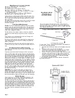
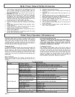


Page 3
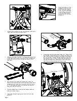
1.
Attach the boom buster bracket to the telescoping brackets,
using the two square u-bolts and 4 whiz nuts. The telescoping
brackets are already mounted to the 3-point frame.
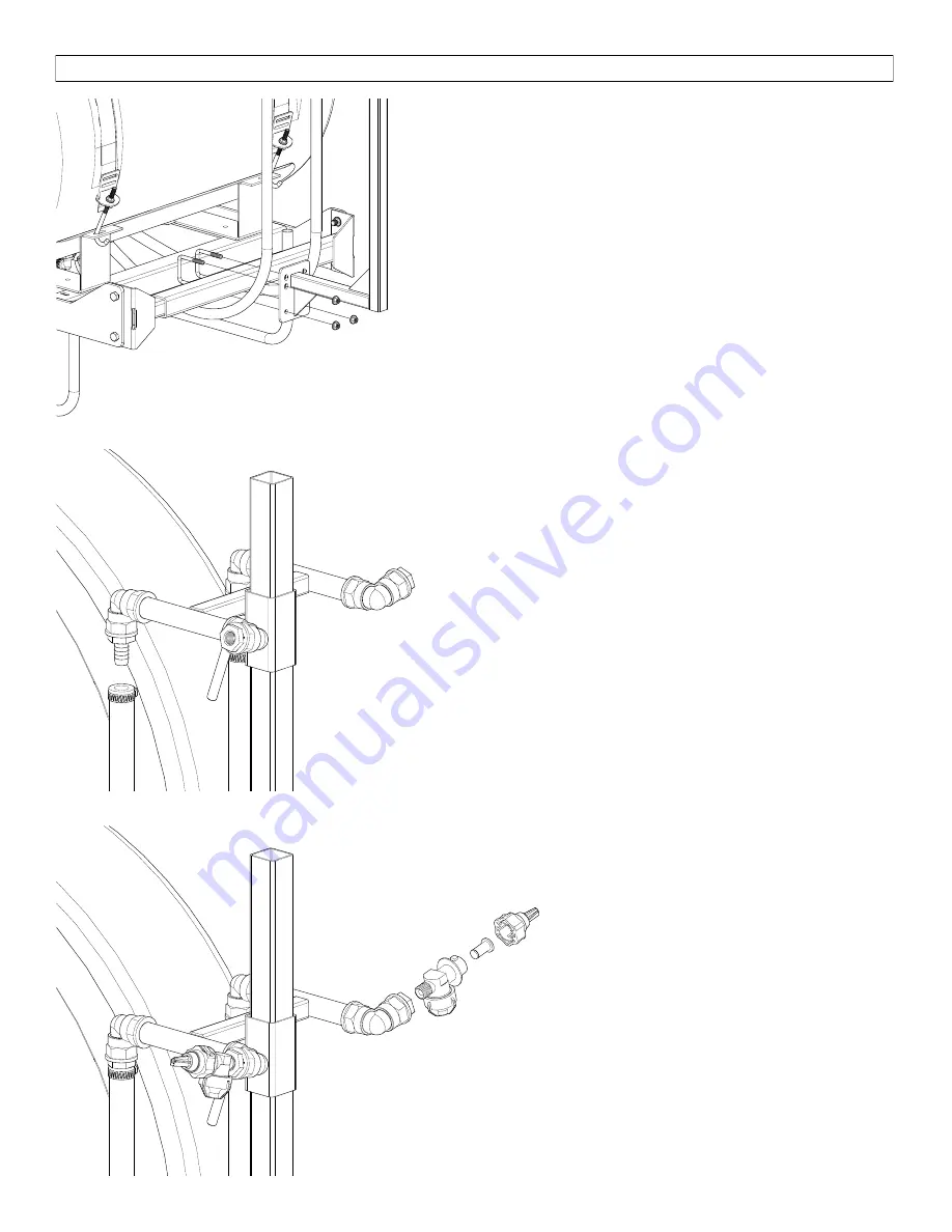
2.
Slide the boom buster subassembly onto the boom buster
bracket. Set the desired height and lock in place with the
handle screw.
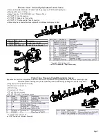
3.
Slip the two 1/2” hose clamps on to the feeder hoses coming
from the valve assembly. With a twisting motion, slide the feed-
er hoses all the way on to the hose barbs and secure with hose
clamps.
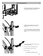
4.
Thread the QJ Diaphragm Check Valve 1/4 MNPT into the
reducer bushing on the elbow.
5.
Insert the blue (50 mesh) nozzle check valve strainer.
6.
Attach the extended range tip and lock in place.
7.
Repeat for other side.
Your Sprayer is now ready to use.
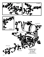
Boom Assembly Instructions


