background image

Page 4 


Assembly Procedure (15-2N-TRL-GS) 


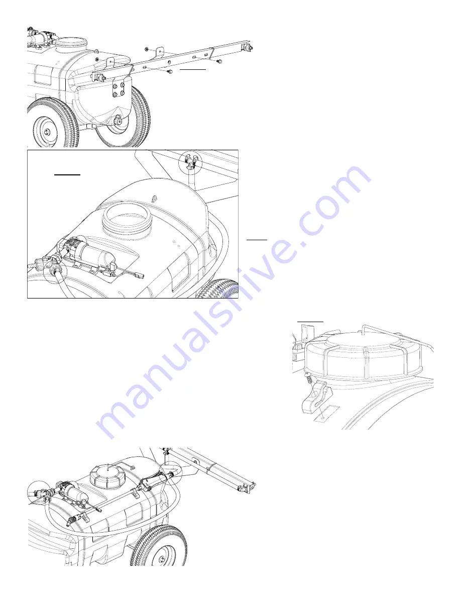
After your trailer boom mount is secured to the tank. 


1/2” socket wrench & wrench is required for this step. 


Attach  the  boom  assembly  to  the  trailer  boom  mount. 

Secure in place with (2) flanged hex bolts and (2) flanged 

hex nuts. 


After your boom is attached to the trailer boom mount, locate 

the feeder hose and the (2) hose clamps from the parts bag. 


Place  the  hose  clamps  loosely  over  each  end  of  the  feeder 

hose. Slip the ends of the hose over the hose barbs on both 

the  y-valve  manifold  and  the  barb  fitting  on  the  nozzle  har-

ness of the boom. Use a twisting motion, if necessary, to get 

the hose fully onto each barb. Bring the hose clamps to the 

connection point and tighten securely. 


NOTE: 

Make  sure  the  boom  feeder  hose  does  not  end  up  on  the 

‘outside’  of  the  spray  wand  hose,  otherwise  unwrapping  the 

spray wand hose from around the tank may be difficult. 


*** The Sprayer should now be ready for use *** 

Screw the lid onto the tank, if not already done. 


Locate the (2) clips and (2) phillips head machine  

screws from the parts bag. 


A phillips head screwdriver is required for this step 


Place  a  screw  through  the  hole  in  the  clip  and  bring  it  up  to  the  tank, 

where the embossments for the clips are  (located on the rear side of the 

tank) 

Secure the clip/screw to the tank. Tighten so that the clip is secure. Do 

this for each clip. 


** DO NOT OVER-TIGHTEN **


The spray wand will snap into the clips once installed. Do not use exces-

sive  force  when  placing  the  spray  wand  into  the  clips,  as  this  could 

cause the clips to break. 

Place a hose clamp loosely over each end of handgun 

hose. Slip the ends of the hose over the hose barb on 

the  y-valve  manifold  and  the back  of  the  spray  wand. 

Use  a  twisting  motion,  if  necessary,  to  get  the  hose 

fully onto each. Bring the hose clamps to the connec-

tion point and tighten securely. 


Step 5 

Step 6 

Step 7 

Summary of Contents for 15-2N-TRL-GS

Page 1: ...OWNER S MANUAL BEFORE RETURNING THIS PRODUCT FOR ANY REASON PLEASE CALL 1 800 831 0027 MONDAY FRIDAY 8 00 AM TO 5 00 PM CST If you should have a question or experience a problem with your Fimco Industries Product Visit our website www fimcoindustries com or call the Toll free number above Our technical support representatives will be happy to help you In most cases a customer service rep can resol...

Page 2: ...m Assembly Tires Wheels Contents of your sprayer s carton 15 2N TRL GS Owner s Manual Tank Lid Lanyard Tank Pre Assembly Axle Kit Contents of Parts Bolt Bag Entry Level Spray Wand 15 Hose Trailer Tongue Trailer Boom Mount ...

Page 3: ...ag Place on top and bottom of tongue and bolt together as shown in Step 2 Tighten the bolts and nuts securely Remove the axle cotter pins and 2 wheels from the carton Slide the axle through the hole in one side of the axle spacer and through the corre sponding hole on the other side Now slide a wheel over the axle and up against the axle spacer Make sure the valve stems of the wheels are facing ou...

Page 4: ...pping the spray wand hose from around the tank may be difficult The Sprayer should now be ready for use Screw the lid onto the tank if not already done Locate the 2 clips and 2 phillips head machine screws from the parts bag A phillips head screwdriver is required for this step Place a screw through the hole in the clip and bring it up to the tank where the embossments for the clips are located on...

Page 5: ...g After Spraying Periodically check the strainer and clean the screen on your intake line Proper care and maintenance will prolong the life of your sprayer After use drain the tank and store or dispose of chemical properly Fill the sprayer half way with clean water Start the pump and allow the water to pump through the entire plumbing system and nozzles Drain and then refill half full add the reco...

Page 6: ...ime Check for air leaks in supply line Check for debris in the check valve assembly Check for defective check valve Check for clogged strainer filter Check for cracks in the pump housing Check for empty product supply Low Pressure Low Flow Check for leaks in the discharge line Check for restriction in the discharge line Check for debris in nozzle orifice Check for clogged strainer Check for proper...

Page 7: ...ed If it still doesn t run try bypassing the switch in the lead wire or using another lead wire Even if a tester shows power to the pressure switch it still could be the switch in the wire that is causing the problem If still not responsive use a voltmeter or electrical tester to make sure you are getting power to the head of the pump as it could possibly be something in one of the wires or even t...

Page 8: ...Page 8 Exploded View Parts List 15 2N TRL GS 5303198 Y Valve Detail ...

Page 9: ... critical factor is to achieve a minimum 30 overlap Excellent spray distribution for uniform coverage along the boom Nozzle design incorporates a pre orifice to produce larger droplets for less drift 2 Nozzle Boom Assembly Exploded View Parts List For the safest and most efficient chemical application you will need to calibrate your sprayer using the tip and speed charts Once you have deter mined ...

Page 10: ...obtain warranty service under this Limited Warranty you must 1 provide written notice to Fimco Ind of the defect during the Warranty Period and within thirty 30 days after the defect becomes apparent or the repair becomes necessary at the following address Fimco Ind 1000 Fimco Lane North Sioux City SD 57049 and 2 make the Equipment available to Fimco Ind or an authorized dealer within a reasonable...

Reviews: