


Page 2
Information About the Sprayer
Roller pumps are positive displacement pumps, which means that
the entire solution being pumped must go somewhere or the pump
will break. In this roller pumping system, solution is drawn from the
tank and forced to a planned source, such as boom nozzles or hand-
gun. The pressure is controlled by a pressure relief valve, which is a
spring-loaded device that controls the amount of fluid bypassed
(recirculated) to the tank. The gray handle is to be tightened to in-
crease pressure and loosened to decrease pressure.
The ‘directo-valve’ is the on/off control which allows the operator to
manually control the solution going to the boom.
IMPORTANT:
Remove tank lid and be sure the tank is
clean and free of any foreign material. Rinse tank out of any
tank residue before filling with water to test.
Tip Information
Important note about tips:
When you refer to the rate charts found
in this owners manual, these rates are based on water. Please read
this tip selection section carefully before attempting to operate your
boom assembly.
The selection of proper tips for the boom is determined by the gallon
per acre (GPA) requirement which is specified on the chemical label.
The following characteristics also have a determining factor and must
be considered.
1.
Speed of spraying (MPH).
2.
Boom nozzle spacing (specified in inches).
3.
Solution weight and conversion factor (CF)
4.
Gallons of solution to be sprayed per acre.
5.
Spraying pressure.
Useful Formulas:
GPM = Gallons Per Minute
GPA = Gallons Per Acre
MPH = Miles Per Hour
Calibration
Chemical labels may show application rates in gallons per acre, gal-
lons per 1000 square feet or gallons per 100 square feet. You will
note that the tip chart (later in this manual) shows 2 of these rating
systems. Once you know how much you are going to spray, then
determine (from the tip chart) the spraying pressure (PSI), and the
spraying speed (MPH).
Determining the proper speed of the pulling vehicle can be done by
marking off 100, 200 & 300 feet. The speed chart indicates the num-
ber of seconds it takes to travel the distances. Set the throttle and
with a running start, travel the distances. Adjust the throttle until you
travel the distances in the number of seconds indicated by the speed
chart. Once you have reached the throttle setting needed, mark the
throttle location so you can stop and go again, returning to the same
speed.
Add water and proper amount of chemical to the tank and drive to the
starting place for spraying
Using the Boom Nozzles
Four things must be considered before spraying with the boom.
How much chemical must be mixed in the tank.
Rate of spray (gallons per acre to be sprayed).
What pressure (p.s.i.) will be used.
Speed traveled (mph) while spraying.
Refer to the chemical label to determine your chemical mixture
See the tip chart to determine the pressure to be used. The
chart will also show the speed used when spraying.
Start the pump and open the valve to the boom nozzles.
Check the spray pattern. Usually you can see the coverage
better on a solid concrete surface, such as a driveway.
Spraying Solutions Other Than Water
Since all the tabulations are based on spraying water, which weighs
8.34 lbs. per USA gallon, conversion factors must be used when
spraying solutions which are heavier or lighter than water. To deter-
mine the proper size nozzle for the solution to be sprayed, first multi-
ply the desired GPM or GPA of solution by the rate conversion factor.
Then use the new converted GPM or GPA rate to select the proper
size nozzle.
Example:
Desired application rate is 20 GPA of 28% Nitrogen.
Determine the correct nozzle size as follows:
GPA (Solution) x Conversion Factor = GPA
20 GPA (28%) x 1.13 + 22.6 GPA (Water)
The applicator should choose a nozzle size that will supply 22.6 GPA
of water at the desired pressure.
Miscellaneous Conversion Factors
One Acre = 43,560 square feet = 0.405 Hectare
One Hectare = 2.471 Acres
One Gallon Per Acre = 9.35 Liters Per Hectare
One Mile = 5,280 Feet = 1,610 Meters = 1.61 Kilometers
One Gallon = 128 Fluid Ounces = 8 Pints = 4 Quarts = 3.79 Liters =
0.83 Imperial Gallons
One Pound Per Square Inch = 0.069 bar. = 6.895 Kilopascals
One Mile Per Hour = 1.609 Kilometers Per Hour
Higher pressure not only increases the flow rate of the nozzle, but it
also influences the droplet size and the rate of orifice wear. As pres-
sure is increased, the droplet size decreases and the rate of orifice
wear is increased.
The values given in the tabulation section of this owners manual
indicate the most commonly used pressure ranges for the associated
spray tips.
Speed in M.P.H.
(Miles Per Hour)
100 Ft.
200 Ft.
300 Ft.
1.0
68 sec.
136
205
2.0
34
68
102
3.0
23
45
68
4.0
17
34
51
5.0
14
27
41
6.0
11
23
34
7.0
9.7
19
29
8.0
8.5
17
26
9.0
7.6
15
23
10.0
6.8
14
20
Speed Chart
Time Required in seconds to travel a distance of
Weight of Solution
Specific
Gravity
Conversion
Factors
7.0 lbs. per gallon
.84
.92
8.0 lbs. per gallon
.96
.98
8.345 lbs. per gallon
(Water)
1.00
1.00
9.0 lbs. per gallon
1.08
1.04
10.0 lbs. per gallon
1.20
1.10
10.66 lbs. per gallon
(28% Nitrogen)
1.28
1.13
11.0 lbs. per gallon
1.32
1.15
12.0 lbs. per gallon
1.44
1.20
14.0 lbs. per gallon
1.68
1.30
Spray
Angle
20"
Spacing
30"
Spacing
40"
Spacing
TeeJet (Flat Spray)
65°
22"-24"
33"-35"
NR*
TeeJet (XR TeeJet)
80°
17"-19"
26"-28"
NR*
TeeJet (XR TeeJet)
110°
12"-14"
16"-18"
NR*
FloodJet
120°
***
***
***
* Not Recommended
*** Wide Angle Spray Tip is influenced by nozzle orientation.
The critical factor is to achieve a double spray patter overlap.
Suggested Minimum Spray Heights
Nozzle Type
Nozzle Height
1
MPH
2
MPH
3
MPH
4
MPH
5
MPH
6
MPH
8
MPH
15
.18
53.6
26.8
17.8
13.4
10.7
8.9
6.7
20
.21
62.4
31.2
20.8
15.6
12.5
10.4
7.8
30
.26
77.2
38.6
25.8
19.3
15.4
12.9
9.7
40
.30
88.0
44.0
29.8
22.0
17.8
14.9
11.1
1
MPH
2
MPH
3
MPH
4
MPH
5
MPH
6
MPH
8
MPH
15
.18
.61
.41
.31
.24
20
.21
.71
.48
.36
.29
30
.26
.88
.59
.44
.35
40
.30
1.0
.68
.51
.41
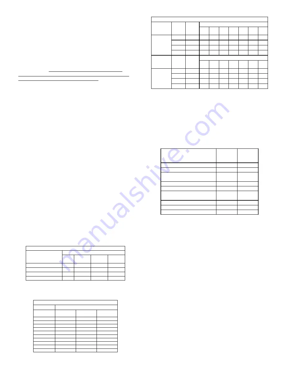
AIXR11003VP
Spray Tip Rate Chart (20" Spacing)
Tip
No.
Pressure
(psi)
Capacity
(GPM)
Gal. Per Acre - Based on Water
Tip
No.
Pressure
(psi)
Capacity
(GPM)
Gal. Per 1000 Sq. Ft. - Based on Water
AIXR11003VP


