background image

Page 2 


3. 

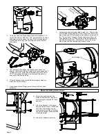
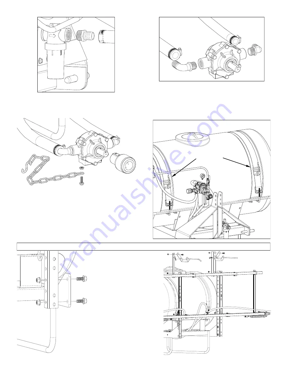
Using a good quality thread sealant, carefully thread the 1” fit-

ting into the strainer. Find the 1” x 36” pump feeder hose. Slip a 

hose clamp onto the ends of the hose. With a twisting motion, 

slip the hose all the way onto the fitting and secure with the 

hose clamp. 

4. 

Using a good quality thread sealant, thread the 1” fitting into the 

inlet (IN) side of the pump and the 3/4” fitting to the outlet (OUT) 

side of the pump. With a twisting motion, attach the other end of 

the 1” hose to the 1” fitting on the inlet to the pump. Slip a 3/4” 

hose clamp onto the 3/4” hose coming off the valve assembly 

and with a twisting motion, attach the 3/4” hose to the output 

side of the pump and securing with the hose clamp.  

5. 

The roller pump IS included with the assembly. Attach the 

adapter, the torque chain and S-hook to the pump as needed. It 

is intended for your pump to be mounted directly to the tractor 

PTO. The torque chain needs to be secured to the tractor to 

keep your pump from spinning.  


6. 

Wrap the handgun hose around the hose hangers which are 

attached to the tank straps.  


7. 

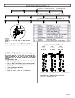
Using sealant thread the gauge into the top of the tee valve  

assembly. 

8. 

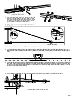
Mount the upright angles to the    

inside of the mounts on the 3-point 

carrier using the supplied 1/2” bolts 

and nuts.    


9. 

Attach the backrack to the upright 

angles using the square U-bolts and 

nuts. Note: the backrack can be 

mounted in either a high or low posi-

tion and the uprights can be adjusted 

for desired height.   


10.  Attach the U-brackets as shown. 

Boom Assembly Instructions 

Hose Hangers 

Inle

t to

 Pu

mp


Ou

tlet t

o Va

lve


As

sem

bly


1” 

3/4” 

Summary of Contents for 300-3PT-17N

Page 1: ...r to give the following information Correct Part Description and or part number Model number and Serial Number Part descriptions and numbers can be obtained from the illustrated parts list section s of this manual General Information Thank you for purchasing this product The purpose of this manual is to assist you in operating and maintaining your 3 Point sprayer Retain a copy of your receipt for ...

Page 2: ...with the hose clamp 5 The roller pump IS included with the assembly Attach the adapter the torque chain and S hook to the pump as needed It is intended for your pump to be mounted directly to the tractor PTO The torque chain needs to be secured to the tractor to keep your pump from spinning 6 Wrap the handgun hose around the hose hangers which are attached to the tank straps 7 Using sealant thread...

Page 3: ...cure with a 3 8 x 1 flange screw Level the outer booms by moving the slide clamps in or out as needed Tighten the bolts in the slide clamps to hold the clamps in place Slide in or out to level 15 Starting with the center section attach the appropriate hose assemblies onto each of the three boom sections Center the center hose assembly on the boom working outward to the ends of the booms the center...

Page 4: ...art the pump and open the valve to the boom nozzles Check the spray pattern Usually you can see the coverage better on a solid concrete surface such as a driveway Spraying Solutions Other Than Water Since all the tabulations are based on spraying water which weighs 8 34 lbs per USA gallon conversion factors must be used when spraying solutions which are heavier or lighter than water To deter mine ...

Page 5: ... the chemical into the tank You may use the handgun to spraying into the solution in order to mix the chemical and water The tips supplied as standard with the sprayer can be used for a wide variety of spraying applications Other tip sizes are available for different coverages The speed and pressure charts shown indicate the rates can be changed considerably by changing speed and pressure The pump...

Page 6: ...tion Aluminum construction with stainless steel and plastic internal parts for maximum corrosion resistance 3 4 NPT Inlet Outlet 3 boom outlet and accessory outlet 1 4 NPT Gauge Port Piston Type Pressure Relief Regulating Valves Bypasses excess fluid Adjustable to maintain control of line pressure at any pressure within the valve operating range Selected pressure setting firmly held in place by lo...

Page 7: ...bows and kinks Make sure all connections are tight and do not leak air Make sure line strainer is free of debris If pump does not self prime disconnect suction hose fill with water and reconnect to liquid source Often a squirt of oil into the ports of the pump will seal clearance and help priming Care of the Pump Proper care and maintenance will keep your pump wear at a minimum and will keep it ru...

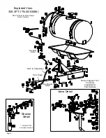
Page 8: ...breakdown Part Numbers IN to Pump Valve Detail Exploded View 300 3PT 17N 5303086 Refer to the parts list next page for part numbers Strainer Detail See Valve Detail See Strainer Detail Available ONLY in complete assembly OUT to Valve Assy ...

Page 9: ... 17N 5303086 Plumbing Detail Hose to RH Nozzle Harness Hose to LH Nozzle Harness Hose to Center Nozzle Harness Bypass Hose H o s e t o V a l v e f r o m P u m p Handgun Hose Available ONLY in complete assembly Hose to Agitator ...

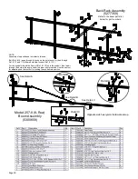
Page 10: ...7 and 1 8 followed with jam locknut Ref 1 10 For the eyebolt thread the first nut Ref 1 13 onto the eyebolt then feed it through the hole in the angle under the lower center section Use the next nut for adjusting and the first nut for locking the eyebolt into position Detail B Detail C See Detail B Model 257 8 8 Row Boom Assembly 5300658 See Detail A Detail A See Detail C Opposite side has typical...

Page 11: ...truction which provides excellent chemical resistance including acids as well as excep tional wear life Compact size to prevent tip damage Removable pre orifice Excellent for systemic products and drift management Ref 20 1 257 8 Center Nozzle Harness 5277761 Ref 20 2 257 8 LH Nozzle Harness 5277806 Ref 20 2 257 8 RH Nozzle Harness 5277806 Nozzle Assemblies consist of Elbow Tee Cross style nozzles ...

Page 12: ...ifice White 1 4 Orifice Color Coded Nozzle Inserts Operation As solution is forced through the agitator the venturi action triples the flow through the agitator The valve in the line may shut off the agitation completely when not needed or it can throttle the amount of solution going to the agitator if too much agitation occurs Orifice Color Orifice P S I Inlet Flow G P M Outlet Flow G P M Black 1...

Page 13: ...Page 13 NOTES ...
Page 14: ...ited Warranty you must 1 provide written notice to Fimco Inc of the defect during the Warranty Period and within thirty 30 days after the defect becomes apparent or the repair becomes necessary at the following address Fimco Inc 1000 Fimco Lane North Sioux City SD 57049 and 2 make the Equipment available to Fimco Inc or an authorized dealer within a reasonable period of time For more information a...

Reviews: