


Page 5
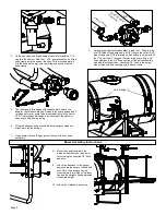
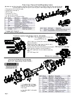
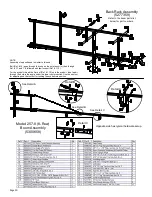
A torque chain, ‘S’ hook, nut and bolt are included in this assembly to
secure your pump during operation.
1.
Attach one end of the torque chain over the threaded stem of the
bolt
2.
Thread the whiz nut onto the bolt. Hand-tighten
3.
Thread the bolt, chain and nut ‘pre-assembly’ into the threaded
hole on the underside of the pump. Tighten sufficiently
4.
Affix the ‘S’ Hook to your frame (or hitch). Wrap the chain around
the frame or hitch and ‘S-Hook’ it in place. Make sure this con-
nection is very secure! Not having a good, tight connection may
result in the pump spinning on your PTO shaft and damaging
some components of your sprayer
*** Insure that this connection point will not allow the roller pump to
spin on the PTO shaft ***
Torque Chain Attachment to a Roller Pump
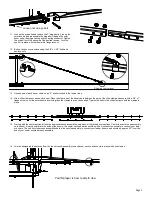
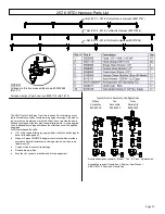
Strap/Buckle Detail
Strap Attachment
to a “Bent” Buckle
The nylon straps are to be inserted in and out of the slots in the
buckle, as shown. Be sure the straps are snug before tightening the
hook bolts. In most cases, it will be necessary to re-tighten the straps
after filling the tank with liquid.
Testing the Sprayer
Attach the sprayer to the tractor 3 point hitch. Mount the pump to the
PTO and affix the torque chain.
NOTE:
It is important for to test your sprayer with plain water before
actual spraying is attempted. This will enable you to familiarize your-
self and check for leaks without the possibility of losing any expen-
sive chemicals.
Fill the tank about 1/2 full with plain water.
Before starting, open the suction line valve (located underneath the
carrier frame), turn the relief valve handle out to lower the line pres-
sure. This will help prime the pump.
CAUTION:
Always be sure that the water (or solution) has reached
the pump before starting your sprayer. If the pump is allowed to run
dry, serious damage to the pump will result.
Always have the pressure line open to the tips so that the air which
may be trapped in the line will be forced (or purged) out.
Start the tractor PTO. Check the entire system for leaks. Once the
pump is primed, the pressure may be increased by turning the han-
dle of the pressure relief valve in. Keep the pressure line open to the
tips when setting the pressure. Set the pressure and then lock the
relief valve handle in place. Shut off the directo-valve and check for
leaks again. Pressure will increase when the pressure line valve is
closed and then return to the preset pressure when the valve is
opened again.
During the testing period, be sure to observe the spray pattern given
by the spray nozzles. If there is any pattern distortion, it will be
necessary to remove and clean the affected tips.
Caution:
Never use a metal object or other sharp item for cleaning a
nozzle tip. It is better to use a nozzle brush (NOT wire brush) or
compressed air for tip cleaning.
Conditions of weather and terrain must be considered when setting
the sprayer. Do not spray on windy days. Protective clothing must be
worn in some cases
Be sure to read the chemical label(s) before application!
Operation
The performance of any agricultural chemical depends upon the
proper application.
Always fill the tank with a desired amount of water first and then add
the chemical slowly, mixing as you pour the chemical into the tank.
You may use the handgun to spraying into the solution in order to
mix the chemical and water.
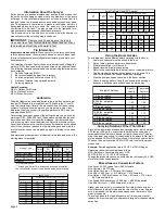
The tips supplied as standard with the sprayer can be used for a
wide variety of spraying applications. Other tip sizes are available for
different coverages. The speed and pressure charts shown indicate
the rates can be changed considerably by changing speed and
pressure. The pumping system draws solution from the tank through
the strainer/filter and to the pump. The pump forces the solution
under pressure to the boom nozzles.
Tank Care & Maintenance
Warning:
Do not use the tank as a container for fuel oils, kerosene,
gasoline or any other petroleum distillate product. All polyolefins are
softened and permeated by such products. In an enclosed area the
vaporization of these materials from the outside surface of the tank
could create a dangerous condition.
The tank should not be used as a pressure vessel nor used with
chemicals or solutions having a weight of more than 12 pounds per
gallon.
Store the tank in a dry dark place when not in use. Storage out of
sunlight will prolong the life of the tank.
Do not drop, strike or kick the tank, especially at low temperatures.
Tanks become brittle and are subject to cracking at temperatures
below 20° Fahrenheit.
Maintenance During/After Spraying
Periodically close the suction line valve and check the strainer and
clean the screen.
Proper care and maintenance will prolong the life of your sprayer.
After use, fill the sprayer tank part way with water. Start the sprayer
and allow the clear water to be pumped through the plumbing system
and out through the spray nozzles. Refill the tank about half full with
plain water and use FIMCO Tank Neutralizer and Cleaner and repeat
cleaning instructions above (If no tank cleaner is available, you may
substitute dish soap for this step, about 1-2 oz. per gallon). Flush the
entire sprayer with the neutralizing/cleaning agent, then flush out one
more time with plain water. Follow the chemical manufacturer’s dis-
posal instructions of all wash or rinsing water. For the boom (if appli-
cable) remove the tips and screens from the nozzle assemblies.
Wash these items out thoroughly. Blow the orifice clean and dry. If
the orifice remains clogged, clean it with a fine bristle (NOT WIRE)
brush or with a toothpick. Do not damage the orifice. Water rinse and
dry the tips before storing.
WARNING:
Some chemicals will damage the pump valves if
allowed to soak untreated for a length of time! ALWAYS flush the
pump as instructed after each use. DO NOT allow chemicals to sit in
the pump for extended times of idleness. Follow the chemical manu-
facturer’s instructions on disposal of all waste water from the sprayer.
Winter Storage
Drain all water out of your sprayer, paying special attention to the
pump, handgun and valve(s). These items are especially prone to
damage from chemicals and freezing weather.
The sprayer should be winterized before storage by pumping a solu-
tion of automotive antifreeze (containing a rust inhibitor) through the
entire plumbing system. This antifreeze solution should remain in the
plumbing system during the winter months. When spring time comes
and you are preparing your sprayer for the spray season, rinse the
entire plumbing system out, clearing the lines of the antifreeze solu-
tion. Proper care and maintenance will prolong the life of your
sprayer.
Summary of Contents for 300-3PT-17N
Page 13: ...Page 13 NOTES ...


