background image

Page 7 


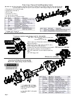
1.  Use  a  pressure  relief  device  on  the  discharge  side  of  the 

pump  to  prevent  damage  from  pressure  buildup  when  the 

pump discharge is blocked or otherwise closed and the pow-

er source is still running. 

2. 

WARNING:

 Never pump flammable or explosive fluids such 

as  gasoline,  fuel  oil,  kerosene,  etc.  Never  use  in  explosive 

atmospheres.  The  pump  should  be  used  only  with  liquids 

compatible  with  the  pump  component  materials.  Failure  to 

follow this warning can result in personal injury and/or prop-

erty damage and will void the product warranty. 

3.  Never pump acids (i.e. acid fertilizer) with Super Rollers!  

4.  Never  run  the  pump  faster  than  maximum  recommended 

speed. 

5.  Never pump at pressures higher than the maximum recom-

mended pressure. 

6.  Never pump liquids at temperatures higher than the recom-

mended maximum temperatures (140°F/60°C). 

7.  Make certain that the power source conforms to the require-

ments of your equipment. 

8.  Provide adequate protection in guarding around the moving 

parts such as the shaft and pulleys. 

Roller Pump General Safety Information 

9.  Disconnect power before servicing. 

10.  Release all pressure within the system before servicing any 

component. 

11.  Drain all liquids from the system before servicing any com-

ponent. 

12.  Check all hoses for weak or worn condition before each use. 

Make certain that all connections are tight and secure. 

13.  Periodically inspect the pump  and the system components. 

Perform routine maintenance as required. 

14.  Never  operate  a  gasoline  engine  in  an  enclosed  area.  Be 

sure the area is well ventilated. 

15.  Use only  pipe, hose and fittings rated for the maximum  psi 

rating of the pump. 

16.  Never  use  pump  for  pumping  water  or  other  liquids  for  hu-

man or animal consumption. 


WARNING:  Never  pump  corrosive  or  abrasive  liquids  as  these 

will cause rapid wear or deterioration of the body, rotor, shaft and 

seals  in  the  pump.  The  pump  should  be  used  on  with  liquids 

compatible with pump component materials. Never exceed maxi-

mum specified rpm and pressure. Never run pump dry. Failure to 

follow this warning will void the product warranty. 


Priming the Pump: 

To help prime the pump, keep the inlet or suction line as short as 

possible with a minimum of bends, elbows and kinks. Make sure 

all  connections  are  tight  and  do  not  leak  air.  Make  sure  line 

strainer is free of debris. If pump does not self-prime, disconnect 

suction hose, fill with water and reconnect to liquid source. Often 

a squirt of oil into the ports of the pump will seal clearance and 

help priming. 


Care of the Pump: 

Proper  care  and  maintenance  will  keep  your  pump  wear  at  a 

minimum and will keep it running smoothly and trouble-free for a 

long time. 

Roller Pump Operation & Maintenance 

Flush the Pump After Each Use 

One  of  the  common  causes  of  faulty  pump  performance  is 

“gumming”  or  corrosion  inside  the  pump.  This  prevents 

rollers  from  moving  freely  in  their  rotor  slots.  Flush  the 

pump with a solution that will neutralize liquid pumped, mix 

according to manufacturer’s directions. 


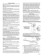
To Prevent Corrosion: 

After  cleaning  pump  as  above,  flush  it  with  a  50-50  solution  of 

permanent-type automotive antifreeze (containing a rust inhibitor) 

and water. A rust inhibitor can also be squirted into the ports of 

the  pump.  Turn  shaft  several  times  to  draw  protective  liquid 

through  pump  and  coat  entire  inner  surface.  Drain  pump  and 

plug  ports  to  keep  out  air  during  storage.  For  short  periods  of 

idleness,  noncorrosive  liquids  may  be  left  in  the  pump,  but  air 

must be kept out. Plug ports or seal port connections. 
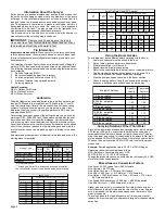
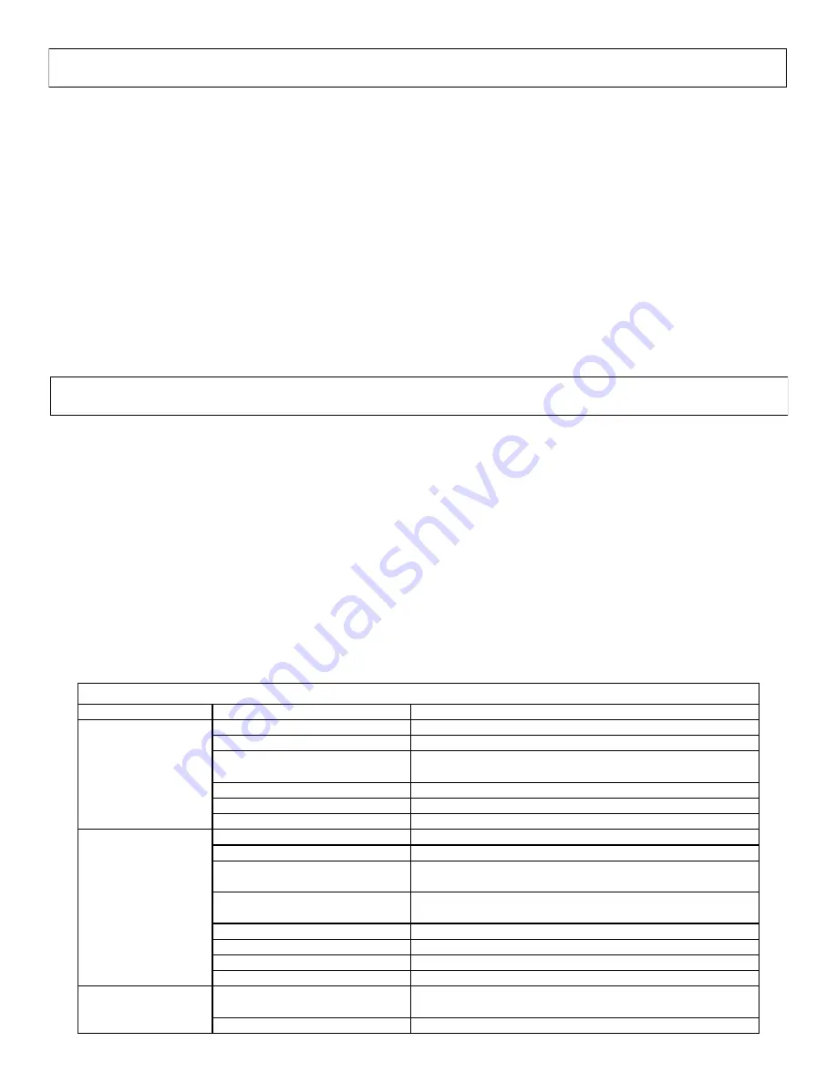
Symptom

Probable Cause(s)

Corrective Action

Leak in suction line

Check hose and fittings for leaks and correct

Obstruction in suction line

Inspect hose for debris or loose inner liner in hose

Suction hose sucked to
bottom or side of tank

Cut a notch or "V" in end of suction hose

Rollers stuck in pump

Disassemble pump and inspect rollers

Pump seals leaking air

Replace seals

Clogged suction strainer

Check strainer and clean it regularly

Kinked or blocked suction hose

Inspect suction hose and repair as necessary

Air leak in inlet side plumbing

Check hose and connections for leaks
Use pipe joint sealant and retighten connections

Relief valve setting too low
or weakened spring

Check relief valve and correct setting

Faulty Gauge

Replace gauge

Pump seals leak air

Replace seals

Nozzle orifices worn

Replace nozzles

Pump worn

Repair pump

Corrosion (rust), scale or residue

Loosen endplate bolts. Squirt oil into ports to help free rotor.
Retighten bolts.

Solid object lodged in pump.

Disassemble pump and remove objects

Troubleshooting

Pump Does Not Prime

Loss of Pressure

Pump will not turn

Summary of Contents for 300-3PT-17N

Page 1: ...r to give the following information Correct Part Description and or part number Model number and Serial Number Part descriptions and numbers can be obtained from the illustrated parts list section s of this manual General Information Thank you for purchasing this product The purpose of this manual is to assist you in operating and maintaining your 3 Point sprayer Retain a copy of your receipt for ...

Page 2: ...with the hose clamp 5 The roller pump IS included with the assembly Attach the adapter the torque chain and S hook to the pump as needed It is intended for your pump to be mounted directly to the tractor PTO The torque chain needs to be secured to the tractor to keep your pump from spinning 6 Wrap the handgun hose around the hose hangers which are attached to the tank straps 7 Using sealant thread...

Page 3: ...cure with a 3 8 x 1 flange screw Level the outer booms by moving the slide clamps in or out as needed Tighten the bolts in the slide clamps to hold the clamps in place Slide in or out to level 15 Starting with the center section attach the appropriate hose assemblies onto each of the three boom sections Center the center hose assembly on the boom working outward to the ends of the booms the center...

Page 4: ...art the pump and open the valve to the boom nozzles Check the spray pattern Usually you can see the coverage better on a solid concrete surface such as a driveway Spraying Solutions Other Than Water Since all the tabulations are based on spraying water which weighs 8 34 lbs per USA gallon conversion factors must be used when spraying solutions which are heavier or lighter than water To deter mine ...

Page 5: ... the chemical into the tank You may use the handgun to spraying into the solution in order to mix the chemical and water The tips supplied as standard with the sprayer can be used for a wide variety of spraying applications Other tip sizes are available for different coverages The speed and pressure charts shown indicate the rates can be changed considerably by changing speed and pressure The pump...

Page 6: ...tion Aluminum construction with stainless steel and plastic internal parts for maximum corrosion resistance 3 4 NPT Inlet Outlet 3 boom outlet and accessory outlet 1 4 NPT Gauge Port Piston Type Pressure Relief Regulating Valves Bypasses excess fluid Adjustable to maintain control of line pressure at any pressure within the valve operating range Selected pressure setting firmly held in place by lo...

Page 7: ...bows and kinks Make sure all connections are tight and do not leak air Make sure line strainer is free of debris If pump does not self prime disconnect suction hose fill with water and reconnect to liquid source Often a squirt of oil into the ports of the pump will seal clearance and help priming Care of the Pump Proper care and maintenance will keep your pump wear at a minimum and will keep it ru...

Page 8: ...breakdown Part Numbers IN to Pump Valve Detail Exploded View 300 3PT 17N 5303086 Refer to the parts list next page for part numbers Strainer Detail See Valve Detail See Strainer Detail Available ONLY in complete assembly OUT to Valve Assy ...

Page 9: ... 17N 5303086 Plumbing Detail Hose to RH Nozzle Harness Hose to LH Nozzle Harness Hose to Center Nozzle Harness Bypass Hose H o s e t o V a l v e f r o m P u m p Handgun Hose Available ONLY in complete assembly Hose to Agitator ...

Page 10: ...7 and 1 8 followed with jam locknut Ref 1 10 For the eyebolt thread the first nut Ref 1 13 onto the eyebolt then feed it through the hole in the angle under the lower center section Use the next nut for adjusting and the first nut for locking the eyebolt into position Detail B Detail C See Detail B Model 257 8 8 Row Boom Assembly 5300658 See Detail A Detail A See Detail C Opposite side has typical...

Page 11: ...truction which provides excellent chemical resistance including acids as well as excep tional wear life Compact size to prevent tip damage Removable pre orifice Excellent for systemic products and drift management Ref 20 1 257 8 Center Nozzle Harness 5277761 Ref 20 2 257 8 LH Nozzle Harness 5277806 Ref 20 2 257 8 RH Nozzle Harness 5277806 Nozzle Assemblies consist of Elbow Tee Cross style nozzles ...

Page 12: ...ifice White 1 4 Orifice Color Coded Nozzle Inserts Operation As solution is forced through the agitator the venturi action triples the flow through the agitator The valve in the line may shut off the agitation completely when not needed or it can throttle the amount of solution going to the agitator if too much agitation occurs Orifice Color Orifice P S I Inlet Flow G P M Outlet Flow G P M Black 1...

Page 13: ...Page 13 NOTES ...

Page 14: ...ited Warranty you must 1 provide written notice to Fimco Inc of the defect during the Warranty Period and within thirty 30 days after the defect becomes apparent or the repair becomes necessary at the following address Fimco Inc 1000 Fimco Lane North Sioux City SD 57049 and 2 make the Equipment available to Fimco Inc or an authorized dealer within a reasonable period of time For more information a...

Reviews: