Page 6
***The Sprayer should now be ready to Test before actual use***
Step 6
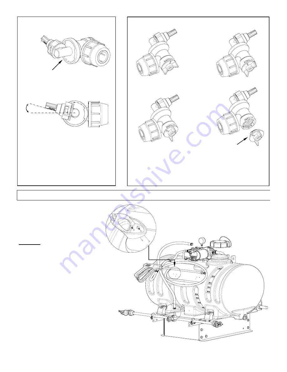
After your nozzle harness is attached to the boom,
attach the boom feeder hose. Place (2) hose clamps
loosely onto each end of the hose, loosely. Slip the
ends of the hose over the hose barbs on both the
manifold and the poly tee fitting on the nozzle
harness. Use a twisting motion, if necessary to get
the hose fully onto each barb. Bring the hose
clamps to the connection point and tighten securely.
Thread the pressure gauge into the manifold.
Hand tight should be sufficient.
Attach hose wraps, as shown.
Finally, thread the lid onto the tank.
Assembly Instructions (Cont.):
15°
End Nozzle Information
(5275122)
This nozzle mounting stem
Has a ratcheting motion.
** Each “click” of the ratcheting motion is approx. 15° **
For proper/optimal spray coverage,
The nozzle must be at a 15° angle
The 15° angle shown will prevent the outer
Nozzles from overlapping with the center nozzle.
“On/Off” Valve Positions
Valve “Open”
Valve “Closed”
Service Position
On/Off Valve Knob
Eliminate line pressure, then pull out
to check diaphragm condition.
Note: The check valve & diaphragm can fall out during transport, if the
knob is not turned to the “ON” or “OFF” position.
Summary of Contents for 3PT-45-12V-BL
Page 13: ...Page 13 NOTES ...


