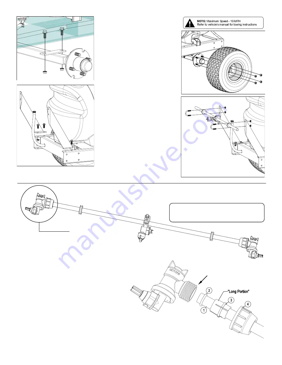
background image

Page 2 


Step 1: 

Attach the axle to the trailer frame with (4) bolts 

& nuts as shown. 


Step 2: 

Slide a wheel onto the hub of the axle and use 

the wheel nuts to hold the wheel in place. Re-

peat for other side. 


Step 3: 

The left and right boom mounting brackets are 

to be mounted on the trailer frame. Use 4 bolts 

and nuts to secure them in place. 


Step 4: 

Center the boom tube on the boom mounts 

and secure in place with the (2) round U-bolts 

and whiz nuts provided. 

Make sure the U-bolts are positioned within the 

grooves of the grommets on the boom tube. 


NOTE: 

The purpose of these grommets is to 

prevent metal-to-metal contact between the U-

bolts, boom tube and boom mounting brackets.


The grommets will ‘compress’ as you tighten 

the whiz locknuts onto the U-bolts. Tighten just 

so that the boom tube will NOT rotate within 

the grommets. Alternate the tightening of the 

locknuts to provide even pressure on the grom-

met. 

**DO NOT OVER TIGHTEN the whiz lock-

nuts, as this may cause the boom tube to 

flatten slightly! 


See Below for end nozzle attachment. 

End Nozzle Assembly Procedure 

For Boomless “Wet” Boom 

Your boom will come with the (2) end nozzle assemblies 

NOT affixed to your boom tube. Follow the instructions 

below to attach these properly to the boom tube, as 

shown. 

Assembled 
End Nozzle 

1.  Start by sliding Item 4, 3, 2 onto the boom tube 

(Item 1) as shown, leaving about 1/2” to 3/4”     

between the end of the boom tube and Item 2. 

Make sure the “Long” portion of Item 3 is facing the 

nozzle end. 

2.  Slide the (complete) end nozzle assembly onto the 

stainless steel boom tube, with a somewhat 

“twisting” motion, so that the end face of the boom 

tube “butts” up against the surface face inside the 

nozzle body. 

3.  Now push the “compression olive” (Item 3) against 

O-ring (Item 2) and slide (both) into the nozzle 

body opening firmly. 

4.  Firmly tighten flynut (Item 4) onto threads of      

nozzle body. 

5.  Repeat for other side. 


NOTE: If water is shooting back on the boom tube, 

item 2 is not in the correct placement. 

Item 2 is shipped inside of 

the end nozzle assembly. 

Remove & place on tube.


Step 5: 

Step 1: 

Step 3: 

Step 2: 

Step 4: 

Summary of Contents for 5301307

Page 1: ... 3 Nozzle Boomless Boom Assembly 30 Spray Coverage Pneumatic Tires 18 x 850 x 8 Maximum Speed 10 MPH Retain a copy of your receipt for your unit as it will be required to validate any warranty service Products are warranted against manufacturer or workmanship defects for one year from date of purchase for home owner usage and 90 days for commercial usage For technical assistance visit our website ...

Page 2: ...lock nuts as this may cause the boom tube to flatten slightly See Below for end nozzle attachment End Nozzle Assembly Procedure For Boomless Wet Boom Your boom will come with the 2 end nozzle assemblies NOT affixed to your boom tube Follow the instructions below to attach these properly to the boom tube as shown Assembled End Nozzle 1 Start by sliding Item 4 3 2 onto the boom tube Item 1 as shown ...

Page 3: ...5122 This nozzle mounting stem Has a ratcheting motion Each click of the ratcheting motion is approx 15 For proper optimal spray coverage The nozzle must be at a 15 angle The 15 angle shown will prevent the outer Nozzles from overlapping with the center nozzle On Off Valve Positions Valve Open Valve Closed Service Position On Off Valve Knob Eliminate line pressure then pull out to check diaphragm ...

Page 4: ...prime the pump keep the inlet or suction line as short as possible with a minimum of bends elbows and kinks Make sure all connections are tight and do not leak air Make sure the line strainer is free of debris If pump does not self prime disconnect suction hose fill with water and reconnect to liquid source Often a squirt of oil into the ports of the pump will seal clearances and help priming Faci...

Page 5: ...ather The sprayer should be winterized before storage by pumping a solution of automotive antifreeze containing a rust inhibitor through the entire plumbing system Make sure to operate the boom and handgun until you see the antifreeze spraying from the nozzles This antifreeze solution should remain in the plumbing system during the winter months It is nearly impossible to drain all of the water fr...

Page 6: ...ows and kinks Make sure all connections are tight and do not leak air Make sure line strainer is free of debris If pump does not self prime disconnect suction hose fill with water and reconnect to liquid source Often a squirt of oil into the ports of the pump will seal clearance and help priming Care of the Pump Proper care and maintenance will keep your pump wear at a minimum and will keep it run...

Page 7: ...mbing Components Tank Valve Assembly 5274939 Refer to Parts List next page for Part Numbers Inlet to Handgun to Boom Return to Tank Bypass See Page 9 for Axle Attachment Hub Detail See Below for Valve Sub Assembly Exploded View Item 10 See Below for Tank Valve Assembly Exploded View Item 2 Refer to Parts List next page for Part Numbers Inlet to Handgun to Boom Bypass Plumbing Components ...

Page 8: ... 5301306 Items 6 7 are not part of the engine pump assembly See above for part numbers Strainer Gasket Screen Cap and bowl ONLY available in complete assembly Refer to Parts List above for Part Numbers Engine Pump Assembly 5278061 ...

Page 9: ... 1 2 spacing All 3 nozzles spraying at the same time will allow a maximum coverage of 30 feet The center nozzle will spray an 80 swath Each of the 3 nozzles has a shutoff valve so you can shut off each nozzle individually This may help in achieving the actual coverage needed for your application 1 2 Bulkhead Fitting TF50DTN Ref 1 1 Refer to Parts List Previous Page for Part Numbers ...

Page 10: ...trol Valve Fimco Mfg Part 5143316 AA6B 5168718 PK AB6B KIT Description Directo Valve AA6B Repair Kit Items Marked Ref Fimco Mfg Part Description Qty 1 5002476 CP36303 PP Poly Body AA6B 1 2 CP36307 PPB Washer 2 3 CP38726 VI Shut Off Washer Viton 1 4 CP36306 302SS Spring 1 5 CP36304 SS Stem 1 6 CP7717 2 108 VI O Ring Viton 1 7 CP7717 2 209 VI O Ring Viton 1 8 5086043 CP36302 PP Poly Body Insert Blac...

Page 11: ...Page 11 NOTES ...

Page 12: ...his Limited Warranty you must 1 provide written notice to Fimco Ind of the defect during the Warranty Period and within thirty 30 days after the defect becomes apparent or the repair becomes necessary at the following address Fimco Ind 1000 Fimco Lane North Sioux City SD 57049 and 2 make the Equipment available to Fimco Ind or an authorized dealer within a reasonable period of time For more inform...

Reviews: