


Page 4
IMPORTANT:
Remove tank lid and be sure the tank is
clean and free of any foreign material. Rinse tank out
of any tank residue before filling with water to test.
NOTE:
It is important to test the sprayer with plain water
before actual spraying is attempted. This will enable you to
check the sprayer for leaks in the plumbing system
Testing the Sprayer
1.
Fill the tank about 1/2 full with plain water.
2.
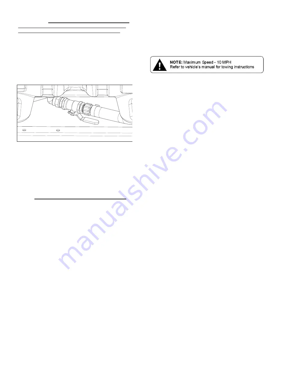
Open the brass valve in the suction line (See Detail A) and
allow water to flow to the pump. The valve is located at this
point to enable the strainer to be taken apart for cleaning, while
solution remains in the tank.
CAUTION:
Always be sure that water (or solution) has reached the
roller pump before starting your sprayer. If the pump is run dry,
serious damage to the pump will result. Do not run your sprayer with
the boom/handgun line closed AND the bypass line closed. Doing
this will damage the pump.
3.
It is always best to start the sprayer at little or no pressure. This
sprayer is equipped with a spring loaded relief valve. Turn the
valve knob out to decrease pressure and in to increase
pressure.
The bypass valve is the “pressure control” for the entire plumbing
system. The more the valve is open, the lower your line pressure.
Almost fully closed provides maximum pressure to your boom and/or
handgun.
NEVER run your system with this valve 100% closed
.
4.
You may now start the engine following the engine
manufacturers instructions. Let the sprayer run at low pressure
until water has reached the handgun and all air has been
purged from the system.
The pressure should now be increased to 30-125 P.S.I. Operate the
sprayer at this increased pressure for 3-5 minutes, thoroughly testing
the unit before adding chemicals.
Caution:
Care must be taken, being sure the handgun is secured in
the operators hand. If this is not done a recoiling action may occur
causing damage or personal injury.
Add water to the tank and drive to the starting place for spraying.
When you are ready to spray, position booms out for spraying and
turn the boom valve to the “on” position. This will start solution
spraying from the tips of the boom. The pressure will decrease
slightly when the boom is spraying. Adjust the pressure by twisting
the gray twist knob on the bypass (pressure relief) valve. Twist
‘clockwise’ to increase pressure , ‘counter-clockwise’ to decrease
pressure.
Read the operating instructions and initially begin spraying by closing
the ‘bypass’ valve and opening the boom line valve. This will enable
the air in the line to be eliminated (purged) through all the tips, while
building pressure. When everything tests all right (no leaks and good
pressure), add the desired chemicals to the mixture and water
combination and start your spraying operation. Adjust the pressure
and spray as you did in the testing procedure.
Conditions of weather and terrain must be considered when setting
the sprayer. Do not spray on windy days. Protective clothing must be
worn in some cases
Be sure to read the chemical label(s) before application!
Information About the Sprayer
In this pumping system, solution is drawn from the tank and forced to
a planned source, such as boom nozzles or handgun. The pressure
is controlled by opening/closing the valve which recirculates solution
back into the tank.
Priming the pump
To help prime the pump, keep the inlet or suction line as short as
possible with a minimum of bends, elbows and kinks. Make sure all
connections are tight and do not leak air. Make sure the line strainer
is free of debris. If pump does not self-prime, disconnect suction
hose, fill with water and reconnect to liquid source. Often a squirt of
oil into the ports of the pump will seal clearances and help priming.
Facing the pump, the suction port is on your left.
Operation
Always fill tank 1/2 full with water first and then add the chemical
slowly, mixing as you pour the chemical into the tank and fill the rest
of the way. You may use the bypass in order to mix the chemical
and water.
The pumping system draws solution from the tank, through the
strainer/filter and to the pump. The pump forces the solution under
pressure to the handgun and/or boom nozzles.
Activate the handgun by squeezing the handle lever
Rotating the adjustable nozzle tip on the handgun will change
the tip pattern from a straight stream to a cone pattern (fine
mist)
This sprayer is designed to be towed behind a garden tractor.
Check the nozzle pattern by spraying water on a concrete surface.
When spraying with either the boom or the handgun, pressure may
be reduced by slowly opening the bypass valve until desired
pressure is achieved. Opening the valve decreases pressure,
closing the valve increases pressure. When spraying with the boom,
the proper method to set the pressure is to open the boom valve
completely and if a lower pressure is desired, then slowly open the
bypass valve until that pressure is obtained.
For the safest and most efficient chemical application, you will need
to calibrate your sprayer using the tip and speed charts. Once you
have determined the proper speed and pressure settings, you will
need to consult your chemical label for the amount of chemical to be
added to the tank. Read the entire label. Use only according to label
directions.
Calibration
Chemical labels may show application rates in gallons per acre,
gallons per 1000 square feet or gallons per 100 square feet. You
will note that the tip chart on the next page shows 3 of these rating
systems.
Once you know how much you are going to spray, then determine
(from the tip chart) the spraying pressure (PSI), and the spraying
speed (MPH).
Determining the proper speed of the pulling vehicle can be done by
marking off 100, 200 & 300 feet. The speed chart (next page)
indicates the number of seconds it takes to travel the distances. Set
the throttle and with a running start, travel the distances. Adjust the
throttle until you travel the distances in the number of seconds
indicated by the speed chart. Once you have reached the throttle
setting needed, mark the throttle location so you can stop and go
again, returning to the same speed.
Add water and proper amount of chemical to the tank and drive to
the starting place for spraying.
Using the Boom Nozzles
Four things must be considered before spraying with the boom.
How much chemical must be mixed in the tank.
Rate of spray (gallons per acre to be sprayed).
What pressure (p.s.i.) will be used.
Speed traveled (mph) while spraying.
Refer to the chemical label to determine your chemical mixture.
See the tip chart to determine the pressure to be used. The
chart will also show the speed used when spraying.
Start the pump and open the valve to the boom nozzles.
Check the spray pattern. Usually you can see the coverage
better on a solid concrete surface, such as a driveway.
Approximate height: 33”
Detail A
Valve Open
Summary of Contents for 5301307
Page 11: ...Page 11 NOTES ...


