background image

Page 5 


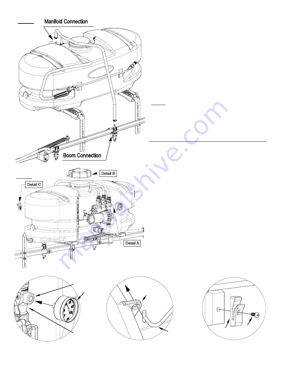
Step 5 

Step 6 

Assembly Procedure (ATV-25-700-QR) 

*** The Sprayer should now be ready for use *** 

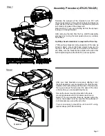
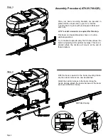
After your nozzle harness is attached to the boom, lo-

cate  the  48”  hose  and  the  (2)  hose  clamps  from  the 

parts bag. 


Place  the  hose  clamps  over  each  end  of  the  hose 

loosely. Slip the ends of the hose over the hose barbs 

on  both  the  manifold  and  the  ’CROSS’  fitting  on  the 

nozzle harness. Use a twisting motion, if necessary, to 

get  the  hose  fully  onto  each  barb.  Bring  the  hose 

clamps to the connection point and tighten securely. 


NOTE: 

Make sure this boom feeder hose does not end up on 

the  ‘outside’  of  the  spray  wand  hose,  otherwise  un-

wrapping  the  spray  wand  hose  from  around  the  tank 

may be difficult. 

Detail A:  Install the pressure gauge. Hand tighten  


securely. 

** DO NOT OVER-TIGHTEN ** 


Detail B:  Screw the lid onto the tank. Place the end of  


the lanyard through the tab in the tank. This 


is so the lid can ‘hang’ off the tank when  


filling/rinsing the tank out. 


Detail C:  Locate the (2) clips and (2) phillips head 


machine screws from the parts bag. 

A phillips head screwdriver is required for this step 

Place a screw through the hole in the clip and bring it 

up  to  the  tank,  where  the  embossments  for  the  clips 

are  (located on the rear side of the tank) 

Secure  the  clip/screw  to  the  tank.  Tighten  so  that  the 

clip is secure. Do this for each clip. 


** DO NOT OVER-TIGHTEN **


The spray wand will snap into the clips once installed. 

Do  not  use  excessive  force  when  placing  the  spray 

wand  into  the  clips,  as  this  could  cause  the  clips  to 

break. 

Lid 

Lanyard 

Lanyard 

Connection 

Tab 

Manifold 

DETAIL B 

DETAIL C 

5053096  5117334 

5167097 

1/4” FPT 

DETAIL A 

Summary of Contents for 5302320

Page 1: ...hould already be attached to the tank IMPORTANT REMINDER This sprayer comes with an On Off shut off valve located at the inlet location of the tank towards the underside See Detail A You must make sure the valve is in the open position before using your sprayer Detail A OWNER S MANUAL BEFORE RETURNING THIS PRODUCT FOR ANY REASON PLEASE CALL 1 800 831 0027 MONDAY FRIDAY 8 00 AM TO 5 00 PM CST If yo...

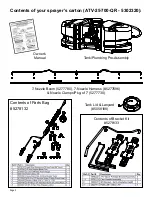
Page 2: ...carton ATV 25 700 QR 5302320 7 Nozzle Boom 5277780 7 Nozzle Harness 5277696 Nozzle Clamps Pkg of 7 5277730 Contents of Parts Bag 5278132 Tank Lid Lanyard 5058188 Contents of Bracket Kit 5278133 Tank Plumbing Pre Assembly Owner s Manual ...

Page 3: ... 4 flat head screws to secure it to the tank The tank will rest on the surface of the brack ets Make sure the brackets are parallel with each other before tightening down the bolts Do not over tighten After your tank brackets are securely attached turn the tank assembly over and position it so that the cam handles which extend beyond the back of the tank are facing you and just hanging over the ed...

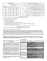
Page 4: ...n be positioned as shown or in a few alternate positions Try to maintain approximately 18 22 inches above the items being sprayed for optimal coverage This is con sidered where the nozzles will mount at the end of these brackets With the boom secured to the boom mounting brack ets the nozzle harness can now be attached Attach the nozzle harness to the boom Using the nozzle clamps attach the nozzle...

Page 5: ...tall the pressure gauge Hand tighten securely DO NOT OVER TIGHTEN Detail B Screw the lid onto the tank Place the end of the lanyard through the tab in the tank This is so the lid can hang off the tank when filling rinsing the tank out Detail C Locate the 2 clips and 2 phillips head machine screws from the parts bag A phillips head screwdriver is required for this step Place a screw through the hol...

Page 6: ...n disconnect the negative black connection and finally the positive red connection The lead wire has an On Off switch to activate the pump is on and O is off Fill the tank part way with water and then add the desired amount of chemical to be sprayed Finish filling tank to proper level Turn the pump on and by depressing the side of the rock er switch The pump is equipped with a pressure switch that...

Page 7: ...orrosion and keep the unit from freezing Note RV antifreeze is non toxic and biodegradable and generally safer for the environment than automotive anti freeze Before storing your sprayer for winter or long term storage thoroughly clean and drain it as much as possible Then pour enough pink RV antifreeze into the tank so that when the pump is turned on you can pump the antifreeze throughout the ent...

Page 8: ... defective check valve Check for clogged strainer filter Check for cracks in the pump housing Check for empty product supply Low Pressure Low Flow Check for leaks in the discharge line Check for restriction in the discharge line Check for debris in nozzle orifice Check for clogged strainer Check for proper voltage try another 12 volt battery Pulsating flow surging Low flow may cause pump to surge ...

Page 9: ...e replaced If it still doesn t run try bypassing the switch in the lead wire or using another lead wire Even if a tester shows power to the pressure switch it still could be the switch in the wire that is causing the problem If still not responsive use a voltmeter or electrical tester to make sure you are getting power to the head of the pump as it could possibly be something in one of the wires o...

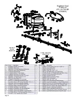
Page 10: ...Page 10 Exploded View Parts List ATV 25 700 QR 5302320 Manifold Detail 5281538 Intake Assembly 5281145 ...

Page 11: ...10 tips and 20 spacing Suggested Minimum Spray Height 16 18 above what is being sprayed to plant not ground Optimum Spray Height 20 110 wide tapered flat spray angle with air induction technology for better drift management Made of 2 piece UHMWPE polymer construction which provides excellent chemical resistance includ ing acids as well as exceptional wear life Compact size to prevent tip damage Ex...

Page 12: ...obtain warranty service under this Limited Warranty you must 1 provide written notice to Fimco Ind of the defect during the Warranty Period and within thirty 30 days after the defect becomes apparent or the repair becomes necessary at the following address Fimco Ind 1000 Fimco Lane North Sioux City SD 57049 and 2 make the Equipment available to Fimco Ind or an authorized dealer within a reasonable...

Reviews: