background image

Page 3 


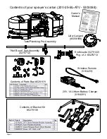
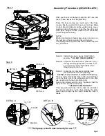
Assembly Procedure (20V-25-BL-ATV) 
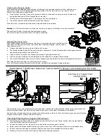
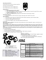
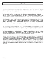
Step 1 

Step 2 

Normally, the sprayer will be mounted on an ATV with the 

pump assembly at the operator’s back and the spray wand 

will  be  at  the  rear  of  the  unit.  Right  Hand  (RH)  and  Left 

Hand (LH) sides of the sprayer are  

determined as if you are standing behind the sprayer,  

looking at it (facing forward) 


After  removing  the  tank  from  the  box,  start  the  assembly 

procedure by turning the tank upside down on a stable, flat 

surface. 


A phillips head screwdriver is required for this step. 


(**)  Mount  tank  brackets  to  the  underside  of  the  tank  as 

shown  in  Step  1.  Use  (4)  flat  head  screws  to  secure  it  to 

the tank. The tank will rest on the surface of the brackets. 

Make sure the brackets are parallel with each other before 

tightening down the bolts. Do not over-tighten. 

Detail A 

After  your  tank  brackets  are  securely  attached,  turn  the 

tank assembly over and position it so that the cam handles 

which  extend  beyond  the  back  of  the  tank  are  facing  you 

and just hanging over the edge of the table or flat surface 

you are assembling this on. 


Secure  the  boom mounting  brackets  to  the  tank  mounting 

brackets with Cam handles as shown in Detail A. You can 

position them as needed within the slot on the bracket. Just 

be  sure  that  the  surfaces  of  both  brackets  are  even  with 

each other. 


You  are  now  ready  to  mount  this  unit  to  an  ATV,  using 

ratchet straps (NOT INCLUDED) 
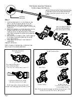
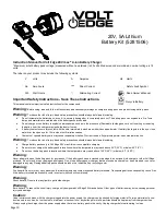
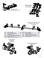
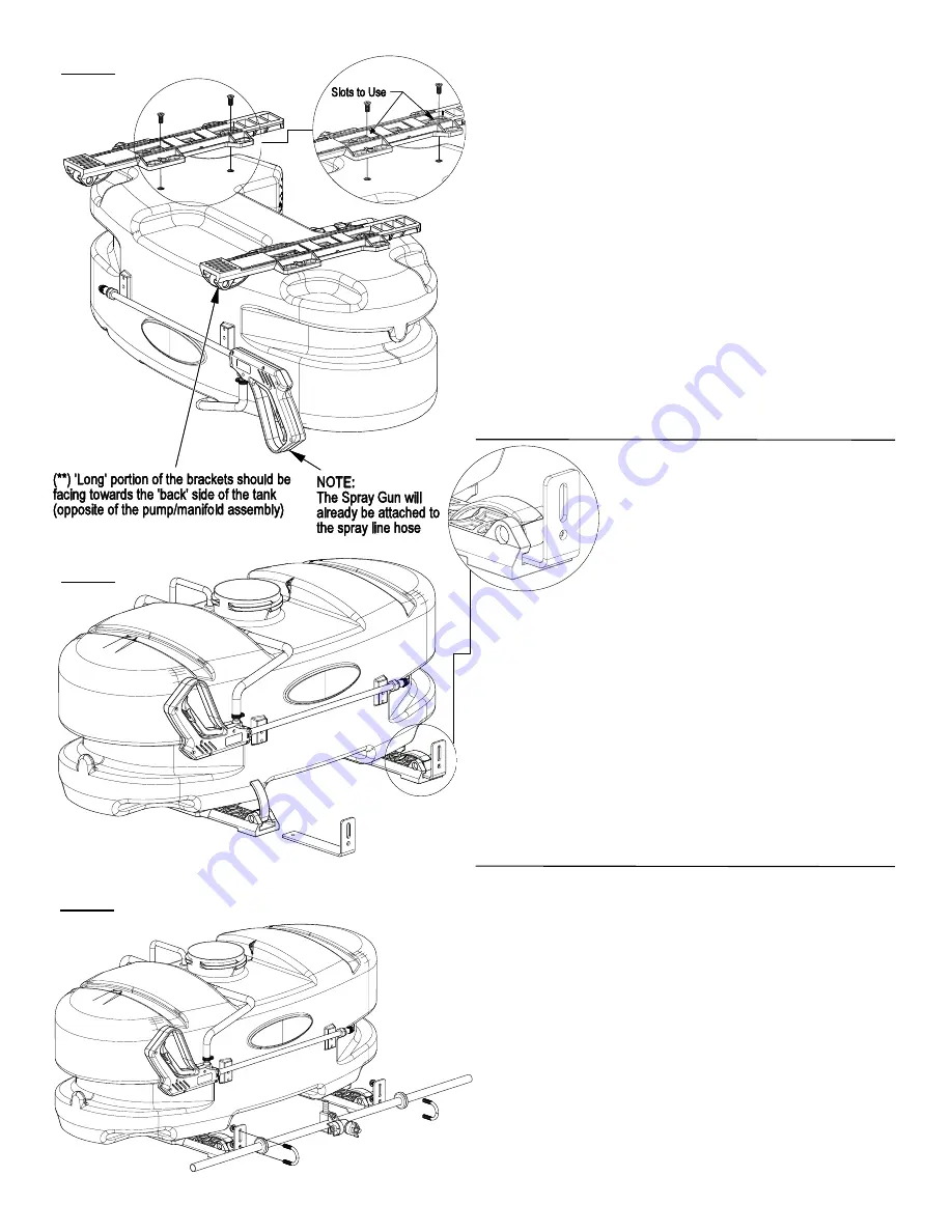
Step 3 

Attach the boom to the boom mounting brackets with 

the (2)  u-bolts and (4) whiz locknuts. Make sure the u-

bolts are positioned within the grooves of the grommets 

on the boom tube 


NOTE: The purpose of these grommets is to pre-

vent metal-to-metal contact between the u-bolts, 

boom tube and boom mounting brackets. 

The grommets will ‘compress’ as you tighten the whiz 

locknuts onto the u-bolts. Tighten just so that the boom 

tube will NOT rotate within the grommets. Alternate the 

tightening of the locknuts to provide even pressure on 

the grommet. 

**DO NOT OVER TIGHTEN the whiz locknuts, as 

this may cause the boom tube to flatten slightly!


Summary of Contents for 5303068

Page 1: ...mes with an On Off shut off valve located at the inlet location of the tank towards the underside See Detail A You must make sure the valve is in the open position before using your sprayer Detail A OWNER S MANUAL BEFORE RETURNING THIS PRODUCT FOR ANY REASON PLEASE CALL 1 800 831 0027 MONDAY FRIDAY 8 00 AM TO 5 00 PM CST If you should have a question or experience a problem with your Fimco Industr...

Page 2: ...3068 Contents of Parts Bag 5281511 Contents of Bracket Kit 5278138 Wet Boom Sub Assembly 5275712 Tank Plumbing Pre Assembly Owner s Manual End Nozzle 5275122 Pkg of 2 5275713 Lid w Lanyard 5058188 Wireless Remote 5164291 20V 1A Lithium Battery Charger 5164281 ...

Page 3: ... handles which extend beyond the back of the tank are facing you and just hanging over the edge of the table or flat surface you are assembling this on Secure the boom mounting brackets to the tank mounting brackets with Cam handles as shown in Detail A You can position them as needed within the slot on the bracket Just be sure that the surfaces of both brackets are even with each other You are no...

Page 4: ...fixed to your boom tube Follow the instructions below to attach these properly to the boom tube as shown Assembled End Nozzle 1 Start by sliding Item 4 3 2 onto the boom tube Item 1 as shown leaving about 1 2 to 3 4 between the end of the boom tube and Item 2 Make sure the Long portion of Item 3 is facing the nozzle end 2 Slide the complete end nozzle assembly onto the stainless steel boom tube wi...

Page 5: ...n securely DO NOT OVER TIGHTEN Detail B Screw the lid onto the tank Place the end of the lanyard through the tab in the tank This is so the lid can hang off the tank when filling rinsing the tank out Detail C Locate the 2 clips and 2 phillips head machine screws from the parts bag A phillips head screwdriver is required for this step Place a screw through the hole in the clip and bring it up to th...

Page 6: ...ff when all discharges are closed The pump will turn back on when one of the following actions occurs Handgun lever is squeezed to spray the handgun Boom valve is opened to broadcast spray with the boom Bypass valve is opened to re circulate solution back into the tank Rotating the adjustable nozzle tip on the handgun will change the tip pattern from a straight stream to a cone pattern fine mist T...

Page 7: ...the tank so that when the pump is turned on you can pump the antifreeze throughout the entire plumbing system including the bypass Make sure to operate the boom and handgun until you see pink fluid spraying from the nozzles Leave any remaining antifreeze in the tank Be fore your next usage rinse the antifreeze from the sprayer with clean water It is nearly impossible to drain all of the water from...

Page 8: ...e Check for restriction in the discharge line Check for debris in nozzle orifice Check for clogged strainer Check for proper voltage try another battery or recharge battery Pulsating flow surging Low flow may cause pump to surge Spray wand is adjusted for a small or fine spray pattern Slightly open bypass if applicable to overcome If needed pressure switch may need to be adjusted adjust a quarter ...

Page 9: ...ve Remove the head of the pump which is held on by 7 screws The first piece inside the head of the pump is called a check valve it s the part responsible for building up pressure and pumping water solution through the lines Clean the check valve under hot soapy water such as a good grade dish soap Give it a very light scrubbing with something like an old toothbrush something with soft bristles The...

Page 10: ...isk of injury basic safety precautions should always be followed including Charge battery packs only in Volt Edge 20V max Lithium ion compatible chargers Do not store or charge the battery pack in locations where the temperature may reach above 95 F 35 C or below 40 F 4 C Do not use the battery pack in locations where the temperature may reach above 120 F 49 C or below 4 F 20 C Warning Never attem...

Page 11: ...y Chargers DOE energy conser vation standards specified in the Code of Federal Regulations at 10 CFR 430 32 z This device complies with CEC Section 1605 1 w of energy efficiency standars for federally regulated battery chargers of California Code of Regulations This device complies with NRCAN EEV CSA C381 2 17 May 2017 and Canada s Energy Efficiency Regulations This device complies with cETLus cer...

Page 12: ...d and it is fully seated 4 Press the power button and confirm the green LED turns on Signaling the power is on 5 Test the remote by pressing the OFF button on the remote and both green and red receiver LEDs will turn on Signaling the power output is off while the power is on 6 Press the ON button on the remote The red LED will turn off and power output will return 7 Press the power button again to...

Page 13: ...f this equipment does cause harmful interference to radio or television reception which can be determined by turning the equipment off and on the user is encouraged to try to correct the interference by one or more of the following measures Reorient or relocate the receiving antenna Increase the separation between the equipment and receiver Connect the equipment into an outlet on a circuit differe...

Page 14: ...Page 14 Exploded View Parts List 20V 25 BL ATV 5303068 ...

Page 15: ...fold Detail See Previous Page for Part Numbers Intake Detail See Previous Page for Part Numbers Boomless Wet Boom Assembly Exploded View Parts List 5275260 Center Nozzle Assembly 5275123 End Nozzle Assembly 5275122 ...

Page 16: ...obtain warranty service under this Limited Warranty you must 1 provide written notice to Fimco Ind of the defect during the Warranty Period and within thirty 30 days after the defect becomes apparent or the repair becomes necessary at the following address Fimco Ind 1000 Fimco Lane North Sioux City SD 57049 and 2 make the Equipment available to Fimco Ind or an authorized dealer within a reasonable...

Reviews: