background image

Page 9 


Remote Button Identification:  


The small LED at the top of remote turns red when transmitting. 


The red LED is also the pairing button. 


The ‘ON’ button will only turn on the Volt Edge Receiver. 


The ‘OFF’ button will only turn off the Volt Edge Receiver. 


Pairing Procedure:


1. 

Ensure the receiver power cord is not connected. 

2. 

Install a charged battery pack into the receiver. 

3. 

Power ON the Volt Edge receiver. Within 15 seconds press and hold the pairing button for 5 seconds. The green LED on the receiver 

will quickly turn off and back on when pairing is successful. 

4. 

Power OFF the Volt Edge receiver. 

5. 

Power ON the Volt Edge receiver and press the OFF and then ON button to confirm pairing is successful. 


Storage Recommendations:


 

The best storage place is one that is cool and dry, away from direct sunlight and excess heat, cold or moisture. 


Remote Capabilities:


 

The remote can control the receiver up to 50 feet away. Obstructions and radio interference can reduce the effective distance. 

 

A remote can be paired to multiple receivers at one time. 

 

A receiver can only be paired to one remote at a time. 

 

A receiver/remote relationship can only be separated by pairing with another remote. 


FCC WARNING: 

Please note that changes or modifications of this product is not expressly approved by the party responsible for compliance, could void the user’s 

authority to operate the equipement. 

FCC STATEMENT: 

NOTE: This equipment has been tested and found to comply with the limits for a Class B digital device, pursuant to Part 15 of the FCC Rules. These 

limits are designed to provide reasonable protection against harmful interference in a residential installation. This equipment generates, uses and can 

readiate radio frequency energy and, if not installed and used in accordance with the instructions, may cause harmful interference to radio communi-

cations. 

However, there is no guarantee that interference will not occur in a particular installation. If this equipment does cause harmful interference to radio or 

television reception, which can be determined by turning the equipment off and on, the user is encouraged to try to correct the interference by one or 

more of the following measures: 

 

Reorient or relocate the receiving antenna. 

 

Increase the separation between the equipment and receiver. 

 

Connect the equipment into an outlet on a circuit different from that to which the receiver is connected. 

 

Consult the dealer or an experienced radio/TV technician for help. 


Declaration of Conformity: 

This device complies with Part 15 of the FCC Rules. Operation is subject 
to the following two conditions: 

 

This device may not cause harmful interference. 

 

This device must accept any interference received, including inter-

ference that may cause undesired operation. 

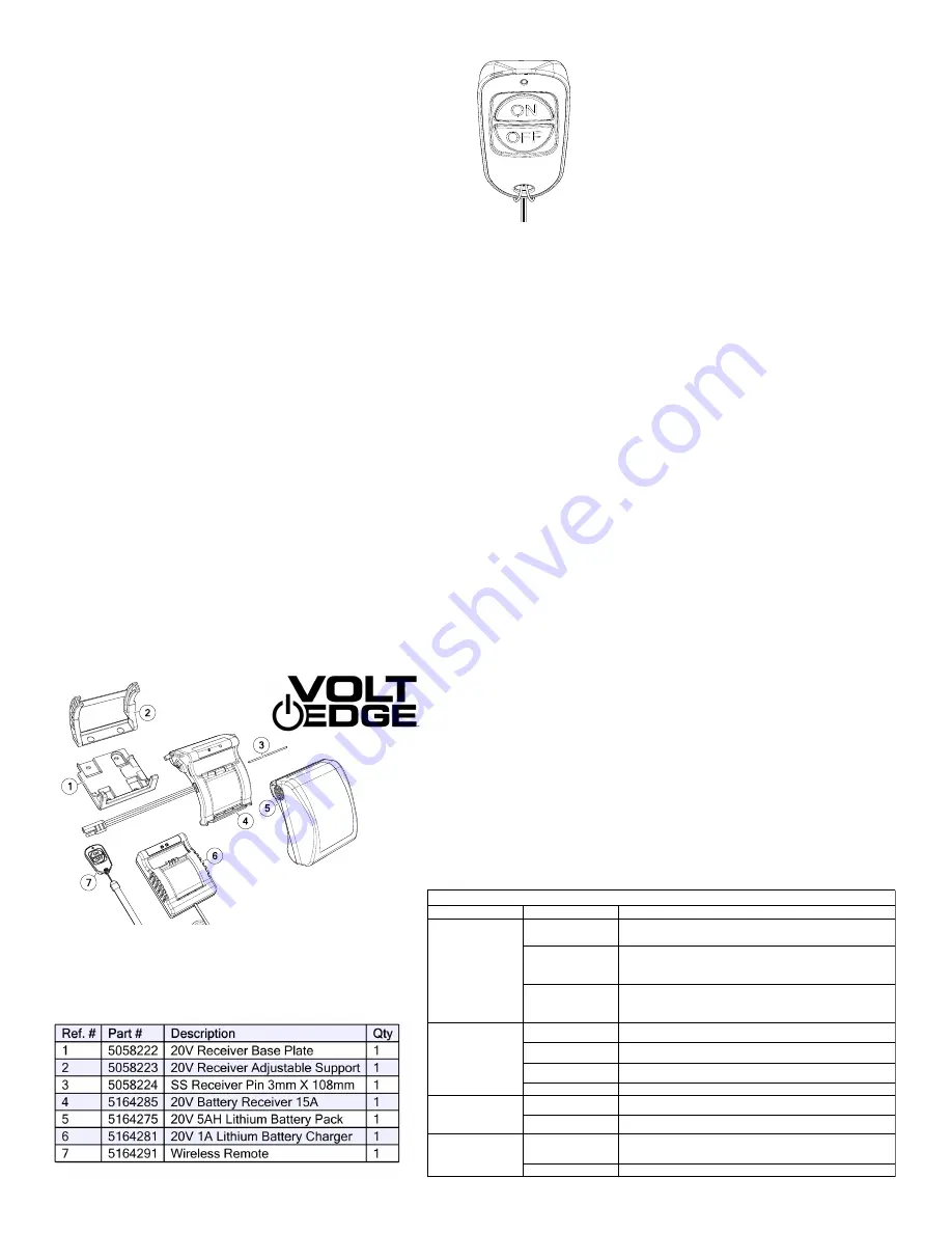
Exploded View/Parts List 

20V, 5A 

Lithium Battery Kit (5281506) 

Problem

Possible Cause

Possible Solution

Charger

not plugged in

Plug charger into a working outlet.
Check outlet with another device.

Temperature is

too hot or too cold

Move charger and battery to a climate-controlled environment and wait for 
the product to reach room temperature.

Battery pack not inserted 

into charger

Remove battery pack and re-install battery pack. Ensure the bottom edge 
of the battery is seated first, then push the clips in.

Remote battery is 

discharged

Replace the battery with CR2032 size button cell battery.

Receiver is not on

The green light must be illuminated on the receiver for the remote to control 
it.

Remote is not

paired with receiver

Follow the Pairing Instructions to pair a remote and receiver.

Radio Interference

Move the receiver and remote away from the electronic interference.

Battery not connected

Remove battery pack and carefully reinstall.

Battery discharged

Remove battery, charge and reinstall.

Bad electrical

connection

Follow wires from receiver to plug. Disconnect and reconnect 
2-pin plug.

Pump fuse is blown

Check fuse on pump wire and replace if necessary.

TROUBLESHOOTING

Remote

does not control the 

receiver

Battery

will not charge

Receiver does not

power pump &

green LED is off

Receiver does not

power pump &

green LED is on

Summary of Contents for 5303069

Page 1: ...RIDAY 8 00 AM TO 5 00 PM CST If you should have a question or experience a problem with your Fimco Industries Product Visit our website www fimcoindustries com or call the Toll free number above Our technical support representatives will be happy to help you In most cases a customer service rep can resolve the problem over the phone To obtain prompt efficient service always remember to give the fo...

Page 2: ...nk part way with water and then add the desired amount of chemical to be sprayed Finish filling tank to proper level Turn the pump on and by depressing the side of the rocker switch The pump is equipped with a pressure switch that is pre set at the factory to shut the pump off when all discharges are closed The pump will turn back on when one of the following actions occurs Handgun lever is squeez...

Page 3: ...from storage drain the antifreeze Fill the tank with fresh water and run through the system Dispose of antifreeze and flush water properly The suction line of your sprayer should contain a siphon tube or intake tube which should be rotated so that it just touches the bottom of the tank surface see Detail Views Reach in and rotate it as needed if not already in this position A shut off valve is thr...

Page 4: ...restriction in the discharge line Check for debris in nozzle orifice Check for clogged strainer Check for proper voltage try another battery or recharge battery Pulsating flow surging Low flow may cause pump to surge Spray wand is adjusted for a small or fine spray pattern Slightly open bypass if applicable to overcome If needed pressure switch may need to be adjusted adjust a quarter turn at a ti...

Page 5: ...o see if the pressure switch is bad Remove the cover off the 1 square box pressure switch on the head of the pump the cover is held on by one phillips head screw This will expose the two red wires With the pump connected to a good 12 volt power source and everything on Slip the two red wires off the terminals and touch them together If the motor runs it means the pressure switch is bad and needs t...

Page 6: ...isk of injury basic safety precautions should always be followed including Charge battery packs only in Volt Edge 20V max Lithium ion compatible chargers Do not store or charge the battery pack in locations where the temperature may reach above 95 F 35 C or below 40 F 4 C Do not use the battery pack in locations where the temperature may reach above 120 F 49 C or below 4 F 20 C Warning Never attem...

Page 7: ... Chargers DOE energy conser vation standards specified in the Code of Federal Regulations at 10 CFR 430 32 z This device complies with CEC Section 1605 1 w of energy efficiency standars for federally regulated battery chargers of California Code of Regulations This device complies with NRCAN EEV CSA C381 2 17 May 2017 and Canada s Energy Efficiency Regulations This device complies with cETLus cert...

Page 8: ... it is fully seated 4 Press the power button and confirm the green LED turns on Signaling the power is on 5 Test the remote by pressing the OFF button on the remote and both green and red receiver LEDs will turn on Signaling the power output is off while the power is on 6 Press the ON button on the remote The red LED will turn off and power output will return 7 Press the power button again to turn...

Page 9: ... this equipment does cause harmful interference to radio or television reception which can be determined by turning the equipment off and on the user is encouraged to try to correct the interference by one or more of the following measures Reorient or relocate the receiving antenna Increase the separation between the equipment and receiver Connect the equipment into an outlet on a circuit differen...

Page 10: ...Page 10 Exploded View Parts List 20V 20 DLX SP 5303069 Intake Assembly 5281145 Manifold Assembly 5281536 ...

Page 11: ...Page 11 Notes ...

Page 12: ...obtain warranty service under this Limited Warranty you must 1 provide written notice to Fimco Ind of the defect during the Warranty Period and within thirty 30 days after the defect becomes apparent or the repair becomes necessary at the following address Fimco Ind 1000 Fimco Lane North Sioux City SD 57049 and 2 make the Equipment available to Fimco Ind or an authorized dealer within a reasonable...

Reviews: