


Page 5
Step 5
Step 6
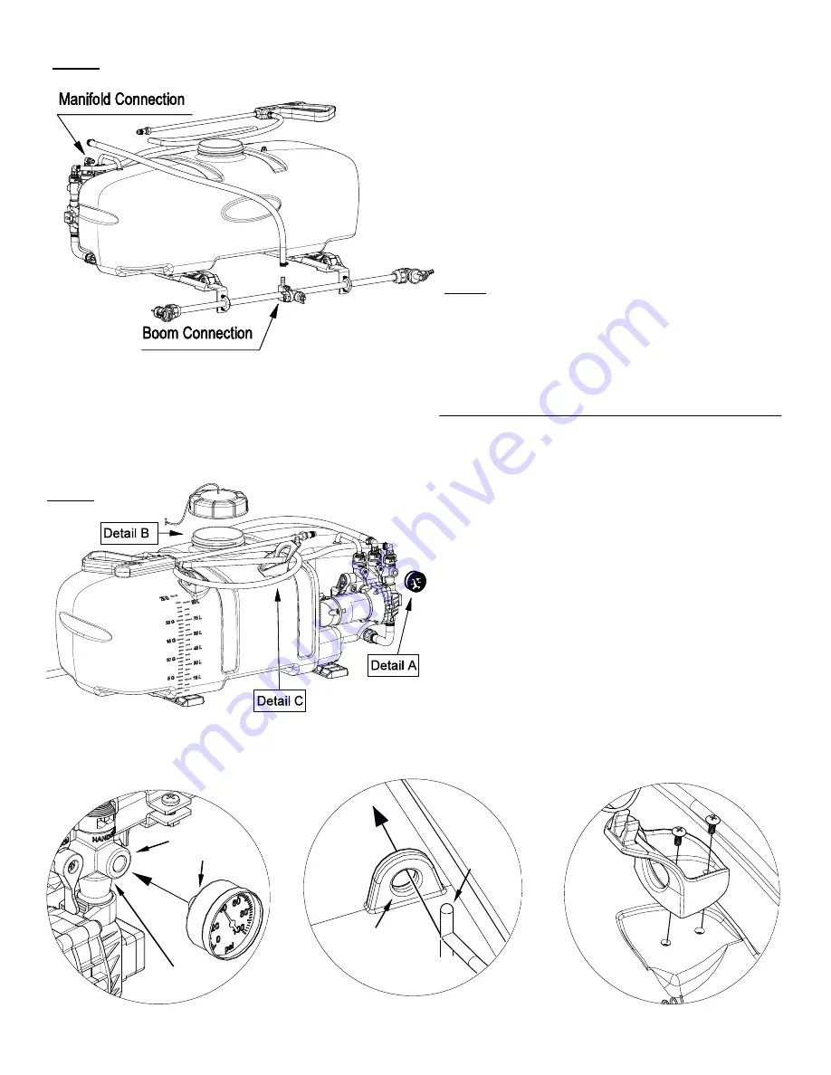
Assembly Procedure (LG-25-BL-ATV)
Manifold
5167097
1/4” FPT
*** The Sprayer should now be ready for use ***
After your boom is attached, locate the 48” hose and
the (2) hose clamps from the parts bag.
Place the hose clamps over each end of the hose
loosely. Slip the ends of the hose over the hose barbs
on both the manifold and on the center nozzle. Use a
twisting motion, if necessary, to get the hose fully onto
each barb. Bring the hose clamps to the connection
point and tighten securely.
NOTE:
Make sure this boom feeder hose does not end up on
the ‘outside’ of the spray wand hose, otherwise un-
wrapping the spray wand hose from around the tank
may be difficult.
Detail A: Install the pressure gauge. Hand tighten
securely.
** DO NOT OVER-TIGHTEN **
Detail B: Screw the lid onto the tank. Place the end of
the lanyard through the tab in the tank. This
is so the lid can ‘hang’ off the tank when
filling/rinsing the tank out.
Detail C: Locate the (2) hose wraps and (4) phillips
head machine screws from the parts bag.
A phillips head screwdriver is required for this step
Place a hose wrap on the tank and secure with two
screws. Tighten so that the hose wrap is secure. Do
this for each hose wrap.
** DO NOT OVER-TIGHTEN **
The spray wand will snap into the hose wraps once
installed. Do not use excessive force when placing the
spray wand into the clips on the hose wraps, as this
could cause the them to break.
Lid
Lanyard
Lanyard
Connection
Tab
DETAIL B
DETAIL C
DETAIL A


