


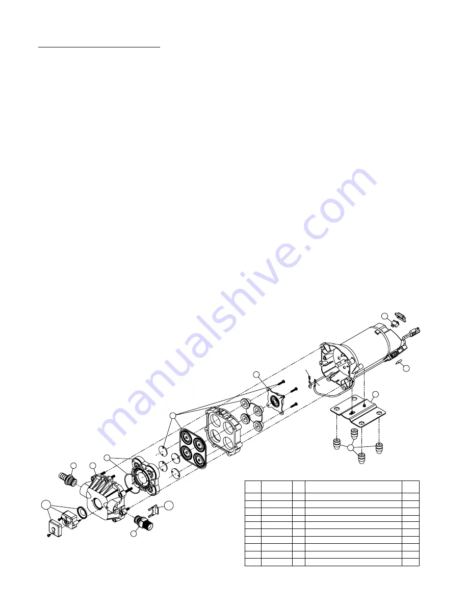
#5275704 Pump
(12 Volt, 11 Amp, 3.8 gpm, 45 psi)
4
3
1
2
7
8
5
5.2
5.1
6
"A"
"B"
*
*
Page 5
- Make sure the bypass line valve is closed, to allow the
pressure to build up in your system.
- Unscrew the head portion of your pump and remove the
check valve assembly from inside. You need to make
sure the O-Ring comes out with this piece as well. (See
the exploded view to help identify these components)
These pieces can be cleaned which, in most cases, will
help restore some, if not most, of your prime. Soak this
check valve in a solution of hot, soapy water. "Dawn"
brand dishsoap works well for this. A little bit of
'scrubbing' with perhaps an old toothbrush may be
required to actually break up any build-up that may be on
the check valve. Rinse off the pieces and replace them
back into your pump. Reassemble the pump. Hook it back
up and test.
Troubleshooting a 3.8 g.p.m. Pump:
Pump will NOT run:
- Check inline fuse on the wires on the pump. If blown,
replace with new fuse. (15 Amp mini-blade fuse #5157206)
- Make sure BOTH on/off switches are in the 'on' position (-).
- Make sure you 12 volt source (battery) is fully charged.
- Insure a tight connection at the battery clips.
If none of the above will work, try pulling wire terminal "A" off
of the spade terminal of the pressure switch, and cross it
over and touch terminal "B". (You will need to remove the
pressure switch cap before doing this) If your pump runs
when you do this, you know you will need to replace your
pressure switch.
Another thing you can try is to take apart the switch box on
the lead wire assembly (#5274443) with the (2) phillips head
screws, and 'hot-wire' it together. Take the (2) wires that are
screwed to the rocker switch, off of the switch and twist
them together. This will insure you are getting the full 12
volts to the pump. If your pump runs after doing this, you will
know that your lead wire assembly needs to be replaced.
Pump runs, but does not prime:
- Check line strainer (screen) at the inlet location, at the
tank. You will need to unscrew the knurled nut to access
this screen. (see exploded view later in this manual) The
ON/OFF valve should be closed while performing this, to
insure you do not lose any solution. Periodically take the
screen at this location out and clean it.
Fittings with an asterisk (*) by
them, come together in a bag,
part #7771831.
(1) 5168832 - 1/2" MNPT
(1) 5168833 - 1/2" Hose Barb
Item
No
Part
Number
Qty Description
List
Price
1
5029092
1 Base Plate (Quad Pump)
9.25
2
5075019
1 Pkg. (4) Grommets
2.99
3
5157206
1 15 Amp Mini Fuse
1.00
4
5157207
1 Rocker Switch
6.99
5
5168821
1 Upper Housing
39.95
5.1 20408-000 1 Pkg. (2) Clips (Port Fitting)
3.41
5.2
5157203
1 Pressure Switch Assembly
23.95
6
5168824
1 Check Valve Kit w/O-Ring & Ferrules
24.99
7
5168826
1 Diaphragm Kit w/Pistons & (4) Screws 19.96
8
5168828
1 Cam/Bearing Kit, w/Set Screw
12.95


