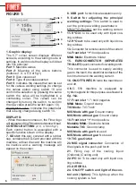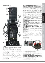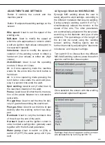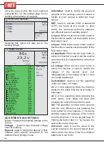
14
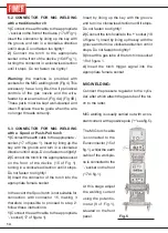
5.2 CONNECTOR FOR MIG WELDING
with a traditional torch
1)
Connect the earth cable to the appropriate
‘-‘ socket on the front of the device (17 of Fig 1).
Insert the connector by lining up the key with
the groove and turn in a clockwise direction
until it stops. Do not fasten too tightly!
2)
Connect the torch to the appropriate
socket in the front of the device (15 di Fig 1),
turning the connector in a clockwise direction
until it stops. Do not fasten too tightly!
Warning:
the machine is provided with
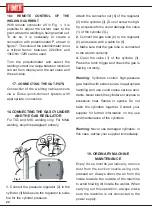
sockets for the MIG welding torch (Fig 4) This
accessory has a long life-time if periodical
controls of the gas nozzle and the wire-
feeder tip are carried out (Fig 4A) (Fig 4B).
These parts must be kept well-cleaned and
intact. Replace the wire guide when the wire
no longer threads correctly.
5.3 CONNECTOR FOR MIG WELDING
with a Spool or Push-Pull torch
1)
Connect the earth cable to the appropriate ‘-‘
socket. (17 of figure 1). Insert by lining up the
key with the groove and turn in a clockwise
direction until it stops. Do not fasten too tightly!
2)
Connect the torch to the appropriate socket
on the front of the device (15 of Fig 1),
turning in a clockwise direction until it stops.
Do not fasten too tightly!
3)
Insert the connector of the torch into the
appropriate female socket.
In the event the Spool torch is not suitable for
connection with connector 15, making it
therefore impossible to proceed to step 2,
follow these instructions:
1)
Connect the earth cable to the appropriate
‘-‘ socket (17 of figure 1).
Insert by lining up the key with the groove
and turn in a clockwise direction until it stops.
Do not fasten too tightly!
2)
Connect the torch cable to the ‘+’ socket (18
of figure 1). Insert by lining up the key with the
groove and turn in a clockwise direction until it
stops. Do not fasten too tightly!
3)
Insert the gas tube of the torch into socket
19 of figure 1.
4)
Insert the torch trigger signal into the
appropriate female socket.
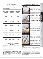
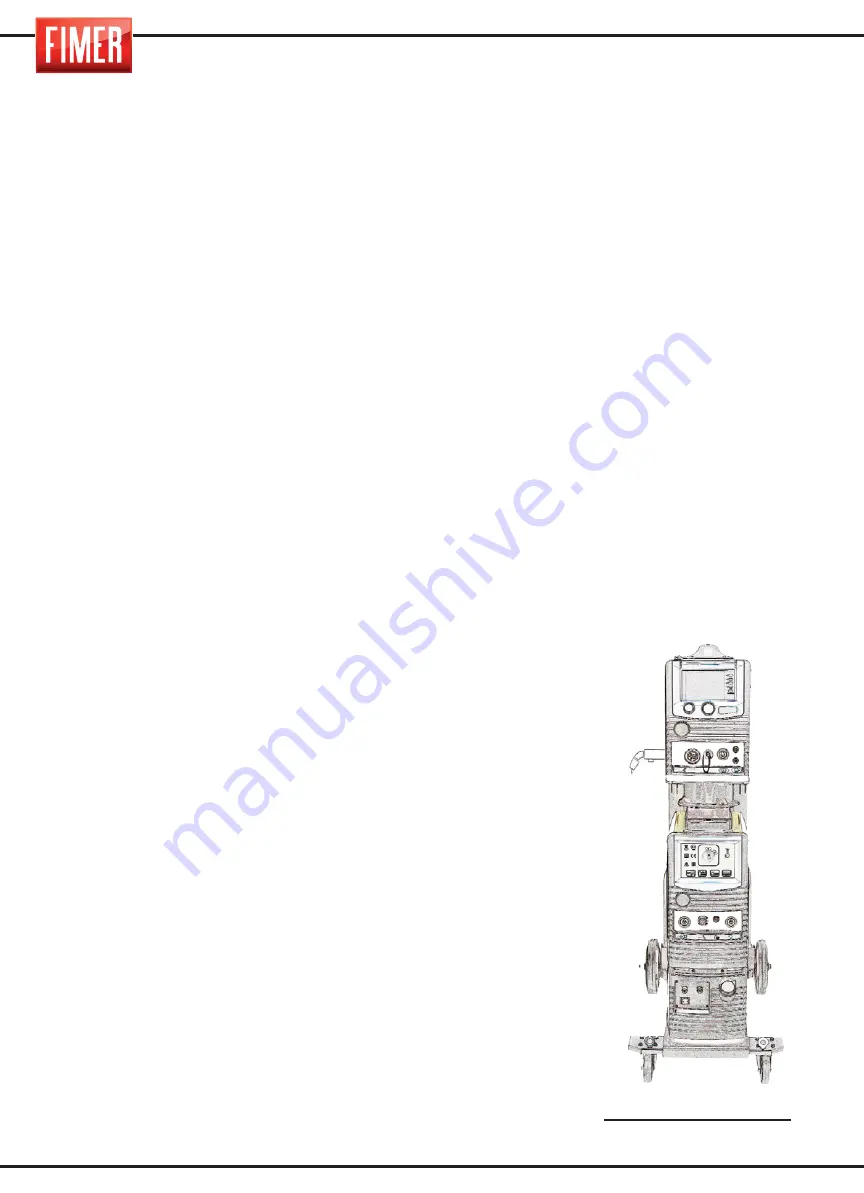
MIG WELDING:
Connect the pressure regulator to the cylin-
der, after which attach the gas tube of the tor-
ch to the latter.
MIG welding is usually carried out with a con-
stant current, with a positive pole (“+ “see fig.5).
The MIG torch cable
is connected to the
Euroconnector (15 of
fig.1), whilst the earth
cable of the workpie-
ce is connected to the
‘-‘ socket on the front
(17 di fig.1).
At this stage adjust
the welding current
using the potentio-
meter (9 of Fig.1),
situated on the front
panel.
Fig.5
Summary of Contents for King 350
Page 4: ...TARGA DATI NOMINAL DATA LEISTUNGSCHILDER PLAQUE DONÉES PLACA DE CARACTERÌSTICAS ...
Page 39: ...3 ...
Page 40: ...4 ...
Page 71: ...3 ...
Page 72: ...4 ...
Page 103: ...3 ...
Page 104: ...4 ...
Page 135: ...3 ...
Page 136: ...4 ...
Page 165: ...NOTE ...
Page 166: ...NOTE ...
Page 168: ......

