


10
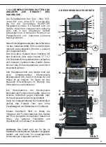
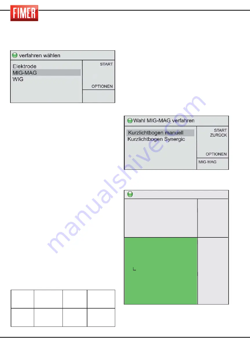
Zur Auswahl dieser Schweißtechnik:
Über den Drehknopf 10 wählen Sie WIG
und drücken zur Bestätigung.
Das MIG/MAG Schweißen (Metal Inert Gas e
Metal Active Gas) ist ein Schweißvorgang mit
kontinuierlichem Draht, der höhere
Stromdichten im Vergleich zum Schweißen
mit beschichteten Elektroden gestattet.
Somit werden größere Penetrationen
erreicht und die Schweißnaht muss beim
Füllen weniger bearbeitet werden.
Der Schweißvorgang erfolgt, indem eine
Metallelektrode aus Draht, die mit
gleichmäßiger Geschwindigkeit ausgegeben
wird und vom Schweißbrennerkopf kontrolliert
wird, in einem Schweißbad aufgelöst wird.
Sobald der Draht zu laufen beginnt und das
zu schweißende Arbeitsstück berührt, wird
ein elektrischer Bogen erzeugt. Dieser
Bogen löst den Draht auf, der sich auf
dem Arbeitsstück niederlässt.
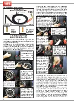
Dieser Schweißvorgang kann die folgenden
Drahtarten verwenden:
1. Volldraht:
Muss stets mit Schutzgas
verwendet werden.
2. Gefüllter Draht für Schweißen mit Gas:
besitzt in seinem Inneren ein Mineralprodukt,
welches die Schweißeigenschaften verbessert
(muss stets mit Gas verwendet werden).
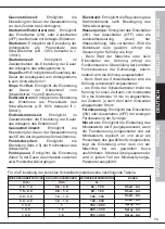
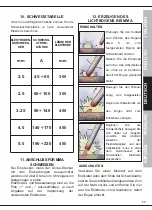
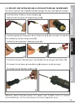
Die Verbindungsstromstärke des
Brennerkopfs und des Massenkabels wird in
der nachfolgenden Tabelle angegeben.
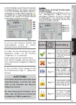
Über den Knopf 9 kann die Potenz des
Geräts ausgewählt werden.
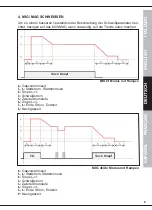
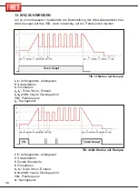
Es gibt zwei Hauptarten zum Schweißen MIG-MAG:
1. Kurzlichtbogen manuell
2. Kurzlichtbogen Synergic
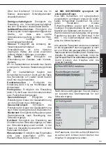
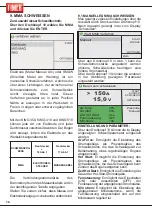
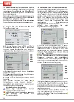
4.1 MIG SCHWEISSEN manueller Short Arc
(Kurzbogen)
Durch Drehen des Drehknopfes 10 kann unter
den verschiedenen Schweißmöglichkeiten
MIG/MAG ausgewählt werden. Durch Drücken
des Knopfes wird die Auswahl bestätigt.
Nach Auswahl gelangt man zum Display
„Schweißen"
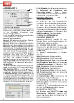
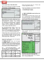
EINSTELLUNG UND PARAMETER:
Durch die 9-Taste können Sie einstellen,
Strom, Leistung Maschine.
SCHWEIS-
SPROZESS
Eurostecker
15 Abb.1
Frontstecker
+
18 Abb .1
Frontstecker
-
17 Abb .1
MIG/MAG
BRENNERKABEL
NICHT
VERWENDET MASSENKABEL
Bereit zum schweissen
START
ZURÜCK
SPEICHERN
GASSPÜLUNG
150
A
15,0
V
>
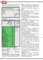
MIG-MAG
S.A.M.
Drahtgeschwindigkeit
SoftStart/Einschleichen
Drossel
2/4 Takt/S-4 Takt
Punktschweißen
Punkt-pause
Gasvorströmzeit
Gasnachströmzeit
Rückbrand
hot start
Wasserpumpe
1,0 m/'
0
0
2t
0,0 s
0,0 s
0,1 s
2,0 s
2,0ms
0
OFF
2,8m/'
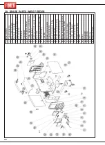
Summary of Contents for King 350
Page 4: ...TARGA DATI NOMINAL DATA LEISTUNGSCHILDER PLAQUE DONÉES PLACA DE CARACTERÌSTICAS ...
Page 39: ...3 ...
Page 40: ...4 ...
Page 71: ...3 ...
Page 72: ...4 ...
Page 103: ...3 ...
Page 104: ...4 ...
Page 135: ...3 ...
Page 136: ...4 ...
Page 165: ...NOTE ...
Page 166: ...NOTE ...
Page 168: ......


