background image

DEVICE DESCRIPTION

11

2

2.2 

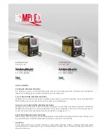
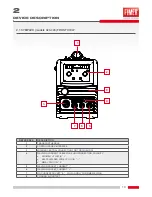
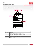
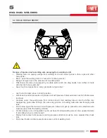
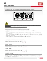
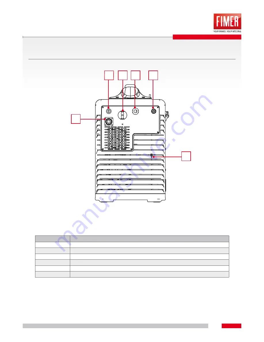
SYMPLEX (models 320-420) REAR VIEW

REFERENCE

DESCRIPTION

1

SAFETY FUSE FOR WATER COOLING UNIT 

4A - T 500V

2

5 POLE SOCKET FOR SUPPLY/SIGNALS WATER COOLING UNIT

3

MAIN SWITCH, MACHINE ON/OFF

4

MAINS CABLE

5

SHIELDING GAS QUICK COUPLING (MIG/MAG)

6

COOLING AIR OUTLET

2

3

1

6

4

5

Summary of Contents for SYMPLEX 320

Page 1: ...SYMPLEX 320 SYMPLEX 420 Ed 2014_11_11 INSTRUCTION MANUAL 910 100 512GB REV00 ...

Page 2: ...placement or resale It is user s responsibility to keep it intact and in good conditions The manufacturer has the right to apply modifies in every moment or without any forewarning Every Fimer product is minded designed and produced in Italy in our sites This is guarantee of high quality and reliability Translation production and adaptation rights total or partial and with every mean photostatic c...

Page 3: ... on top of the market Our production assistance and training site is exclusively on Italian region and we can praise a 100 MADE IN ITALY In addition Fimer has inside a complete chain thanks to an efficient and high quality carpentry department lines of electronic boards and testing assembly department which make possible to create the entire product To be able to reach the best welding processes a...

Page 4: ...the arc is self protected from the powders contained in the core and it is always used a continuous current with direct polarity torch connected to negative pole ELECTRODE MMA MANUAL WELDING MMA welding uses the electric arc generated between consumable electrode and fusion pool It doesn t use any protection gas in fact the atmosphere protection comes from the electrode GOUGING The gouging uses th...

Page 5: ...SYMPLEX 320 SYMPLEX 420 ...

Page 6: ... MMA WELDING____________________________________________________________________________ 23 6 1 CONNECTING THE ELECTRODE HOLDER AND THE EARTH CABLE 23 6 2 WELDING CURRENT MANUAL SELECTION 23 6 3 ARC FORCE 23 6 4 HOT START 23 6 5 ANTISTICKING 23 ALARMS TROUBLESHOOTING_______________________________________________________________ 24 7 1 ERROR MESSAGES 24 CARE AND MAINTENANCE________________________...

Page 7: ...ng Retain this manual for the entire life of the equipment It should be kept within the operator s reach at all times Fires and explosions can seriously injure or cause dama ge Read understand and observe all safety warnings to reduce the risk of death or injury from fire or explo sion Pay particular attention to the fact that even bystanders should be aware of and understand the dangers existing ...

Page 8: ... CABLES Never use damaged cables This applies to both the power and the welding cables DAMAGED CABLES Never remove the unit side panels If the side panels can be opened always checked they are closed tightly before starting any work HIGH VOLTAGE PROTECTION HIGH VOLTAGE PROTECTION Together with the previous instructions the following pre cautions should be strictly observed FIRE PREVENTION FIRE PRE...

Page 9: ...ot expose gas cylinders to excessive heat sour ces sparks hot slag or flames GAS HOSE 1 Check the gas hose is not damaged GAS HOSE 2 Always keep the gas hose well away from the work area ELECTRIC SHOCK Together with the previous instructions the following pre cautions should be strictly observed to reduce the risk of electric shock ELECTRIC SHOCK INJURY DO NOT touch a person suffering from electri...

Page 10: ... 3 MIG MAG CENTRAL CONNECTION FOR TORCH EURO 4 WELDING CURRENT CABLE FOR EURO CONNECTION POLARITY MIG MAG PLUG IN SELF SHIELDED WIRE PLUG IN MMA PLUG IN 0 5 WELDING SOCKET CURRENT 6 WELDING SOCKET CURRENT 7 NO CURRENT SOCKET 0 PLUG IN ONLY FOR MMA WELDING 8 COOLING AIR OUTLET DEVICE DESCRIPTION 4 5 6 7 3 2 1 8 ...

Page 11: ...20 REAR VIEW REFERENCE DESCRIPTION 1 SAFETY FUSE FOR WATER COOLING UNIT 4A T 500V 2 5 POLE SOCKET FOR SUPPLY SIGNALS WATER COOLING UNIT 3 MAIN SWITCH MACHINE ON OFF 4 MAINS CABLE 5 SHIELDING GAS QUICK COUPLING MIG MAG 6 COOLING AIR OUTLET 2 3 1 6 4 5 ...

Page 12: ...ime s Inductance min 1 5 10 1 30 0 40 max 22 35 5 120 20 40 Chart 1 parameters Simplex320 Simplex420 in MIG Simplex320 welding current A Simplex420 welding current A Simplex 320 420 Hot Start Arc Force min 15 15 100 100 max 300 370 200 200 Chart 2 parameters Simplex320 Simplex420 in MMA INTERFACE PANEL 3 6 1 7 5 4 9 8 10 13 12 14 15 2 11 PU3 PU1 PU2 EN1 DL3 DL2 T2 T1 DL1 DL17 EN2 POT4 POT3 ...

Page 13: ...the functioning in 2 or 4 strokes During 2 strokes mode 2s the machine welds for all the time long when torch button is pushed During 4 strokes mode 4s a first pressure on torch button at start the second pressure to stop Pushing once again the button it changes in MMA mode 5 PU2 COOLING UNIT ON OFF BUTTON On MIG MAG mode it allows to switch on or off the cooling unit in case of water cooled torch...

Page 14: ... on top of the torch at the end of welding 11 SOFT START TRIMMER REGULATION It allows to modify the wire approaching speed to obtain a welding trigger softer or speeder 12 DL17 ERROR NOTIFY LED 13 DL1 INVERTER ON MMA MODE NOTIFY LED 14 DL2 MODE TORCH NOTIFY LED 15 DL3 COOLING UNIT ON NOTIFY LED ...

Page 15: ...elding currents Vacant welding currents can cause fires and personal injuries Clean the connecting points Safely connect the earth cable Do not use the structural parts of the piece to weld as welding current return conductors Assure a perfect current conduction 4 3 ELECTRICITY CONNECTION Inappropriate connection risks An inappropriate connection can cause material and personal damages Exclusively...

Page 16: ...Wrong use of protection gas cylinders A wrong use of protection gas regulation can cause hard injuries and death Follow the gas manufacturer indications and the suggestions for pressured gas Install the gas cylinder in the arranged seat and assure it by protection elements Avoid overheating of protection gas cylinder 4 6 MIG MAG WELDING SHIELDING GAS SETTING WELDING PROCESS RECOMMENDED PROTECTION ...

Page 17: ...ite liner In case of wire feeder sheath replacement carefully follow these instructions A B C Torch side remove the gas nozzle A Unscrew the wire guide tip B Connector side C D E F Unscrew the termination nut D E Complete the sheath extraction F Grab the sheath end by a nipper and start to extract it F G B A Insert the new sheath and push it deep inside G Screw in again the wire guide tip on the t...

Page 18: ...fixing and braking unit by hexagon screw into the wire roll housing with 4 complete rotations 4x360 in clockwise NOTE When You make a change of the wire diameter it is necessary to be sure that the correct wire feeder cave is faced inside the machine To make this verify if the diameter value and type of wire are readable facing the external of the machine Reminder rolls are equipped by a V cave ad...

Page 19: ...re Screw in the hex to obtain a good friction If You fix hard the friction is excessive and arrests the normal unrolling of the roll Otherwise a low braking makes the wire unrolls itself accidently at the end of welding Unscrew the knobs of the wire feeder group and let them turn In this way they will lift the upper wire feeders G H I Insert the wire into the wire feeder engi ne capillary tube Let...

Page 20: ... Unlock and overturn pressure unit tension unit with pressure rollers automatic overturn themselves to above Carefully unroll the welding wire from roll and insert it into capillary tube or into the Teflon core equipped by guide tube through the wire entry junction on feeding rolls slots and through guide tube Push below again the tension unit with pressure rollers and get up pressure units electr...

Page 21: ... motor runs at soft start speed Arc ignites after the wire electrode makes contact with the workpiece the welding current flows Change over to pre selected main wire speed STEP 2 Release torch trigger Wire feeder motor stops Arc is extinguished when adjusted wire burn back time expires Gas post flow time passes t1 PRE GAS t2 POST GAS ...

Page 22: ... wire electrode makes contact with the workpiece the welding current flows Change over to pre selected main wire speed STEP 2 Release torch trigger without effects STEP 3 Press torch trigger without effects STEP 4 Release torch trigger Wire feeder motor stops Arc is extinguished when adjusted wire burn back time expires Gas post flow time passes t1 PRE GAS t2 POST GAS I1 WELDING CURRENT ...

Page 23: ...socket and lock it by turning it clockwise Insert the earth cable s connector into either the welding or welding current socket and lock it by turning it clockwise Place polarity cable for euro connection socket into 0 rest position 6 2 WELDING CURRENT MANUAL SELECTION Select welding current through the EN1 knob 6 3 ARC FORCE Select welding current through the POT3 knob 6 4 HOT START Select weldin...

Page 24: ...rs which prevents inverter starting Error solving To cancel the error you need to switch off and switch on again the machine after eliminating the error condition Antisticking error Err StC This error can occurs only when the machine is welding in MMA This error occurs if during the welding process ao the start phase the electrode sticks to the workpiece Error solving The machine will start again ...

Page 25: ... to function when temperature will decrease up to an uncritical value Low coolant level error Err H2O This error can appears only if the machine works in MIG MAG mode If the water cooling unit is switched on the error occours if there are leak in the coolant circuit less water into the tank coolant pump is not working sensor damaged Error solving The machine will start again to function when the e...

Page 26: ...ooling liquid flexible tubes and into their connections Verify the tight position of wire guide elements entry junction guide tube In addition to the control rules here explained it is necessary to observe local laws and disposals 8 3 REPAIRS Repair and maintenance acts must be done only by specialized and authorized persons Otherwise warranty right is declined For everything You need assistance p...

Page 27: ...s Post gas time POST script is visualized It is showed in seconds Default value is 0 1s Changeable interval 0 1 5 seconds Hot start t C script is visualized It indicates the trigger current expressed in Ampere Default value is 370A Changeable interval 150 400 Ampere Hot start time TCS script is visualized It indicates the time of trigger current It is expressed in milliseconds Default value is 8ms...

Page 28: ...ipts To restore MMA parameters default values set ON and confirm by pushing 2S 4S MMA button PU1 9 6 WATER COOLING UNIT SERVICE MENU The water cooling unit is enabled in Simplex 420 and Simplex 320 as default To enter the service menu it is necessary to push at the same time the wire feeder button PU3 and on off water cooling unit button PU2 at the start of the machine until the display turns off ...

Page 29: ...90 007 P It provides the installation of water cooling system WCS1 580 520 053 and toolsbox 580 690 100 P Without water cooling system P it provides only the installation of water cooling system WCS2 580 521 053 without toolsbox WxLxH 570x1090x1010 mm 32 kg WxLxH 475x975x1005 mm 22 kg WxLxH 600x565x1200 mm 30 kg ACESSORIES ...

Page 30: ...ooling unit it isn t possible to install both accessories under the welding machine TOOLSBOX 580 690 100 260x680x260 mm 25 kg 10 3 WATER COOLING UNIT WCS1 WCS2 Depending on the trolley selected you can choose the following units of cooling WCS1 WCS2 580 520 053 580 521 053 2 Ph 400V 260x680x260 mm 25 kg 2 Ph 400V 260x640x260 mm 23 kg ...

Page 31: ... 600 146 Torch F51 H2O 5 m ACCESSORY MMA 489 603 413 Cables set complete 50 mm2 dinse 50 mm2 L 3 2 ROLLS 422 510 002 Roll 0 8 1 0 D 3 V groove steel stainless steel STANDARD 422 520 002 Roll 1 0 1 2 D 37 V groove steel stainless steel included 2x 422 520 003 Roll 1 2 1 6 D 37 V groove steel stainless steel 422 520 004 Roll 0 8 1 0 D 37 U groove aluminium 422 520 051 Roll 1 0 1 2 D 37 U groove alum...

Page 32: ...32 11 NOTE ...

Page 33: ...33 11 NOTE ...

Page 34: ...34 11 NOTE ...

Page 35: ...als may have if not disposed properly potential adverse affects on the environment Presence of this label on the product means it must not be disponed in normal household waste and must be disposed separately As a consumer you are responsible for ensuring that this product is disposed properly If your supplier offers a disposal facility please use it or alternatively contact your local authority c...

Page 36: ... 39 039 6079326 Fax 39 039 6079334 ASSISTENZA TECNICA service welding fimer com LUNEDì VENERDì 09 00 12 30 15 30 17 00 Via J F Kennedy 20871 Vimercate MB Italy Phone 39 039 98981 Fax 39 039 6079334 www fimer com info fimer com ...

Reviews: