21
ESP
AÑOL
FRANÇAIS
DEUTSCH
ENGLISH
IT
ALIANO
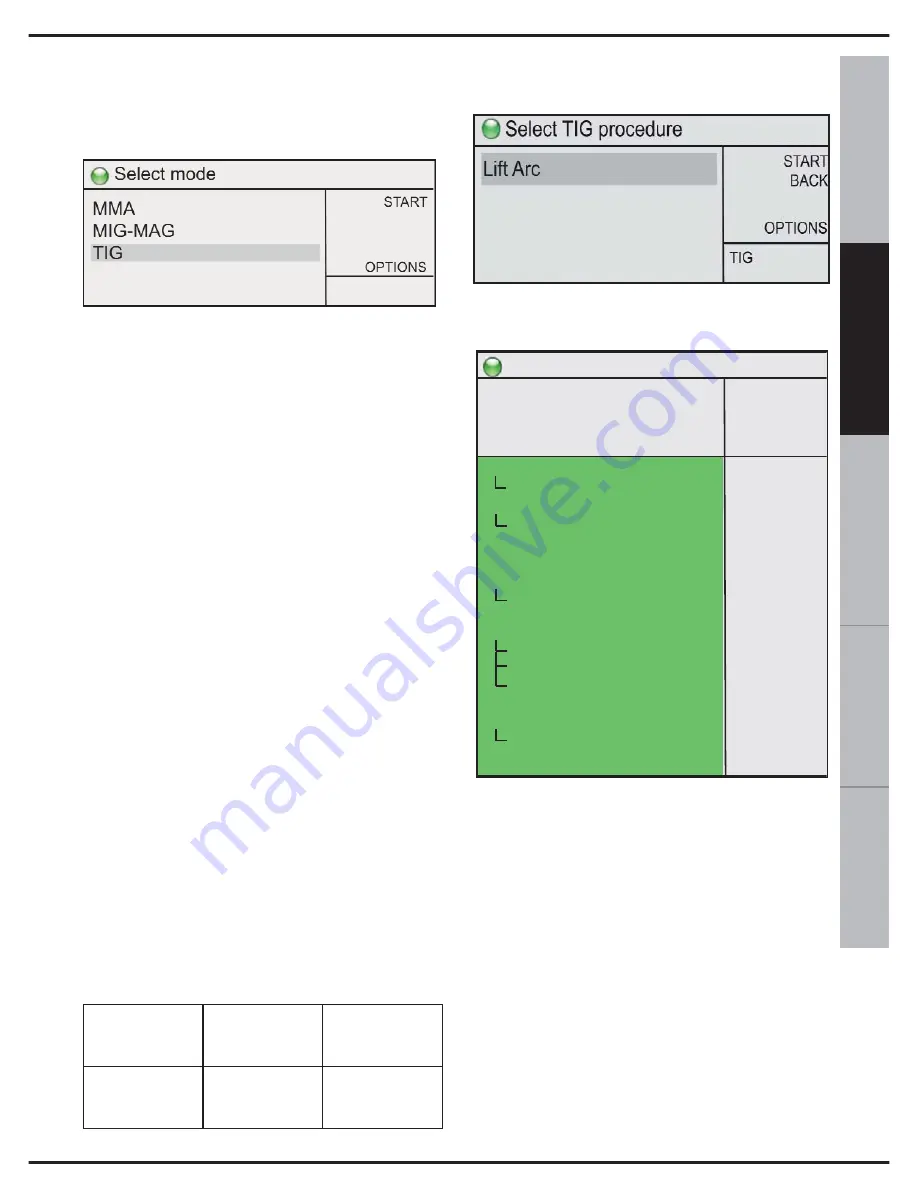
To select this welding mode :
turn switch 10, select TIG and press
confirm.
Inert gas welding with an infusible Tungsten
electrode (TIG: Tungsten Inert Gas) for
short, is a welding procedure whereby the
heat is produced by an arc that strikes
between a tungsten electrode (which is not
consumable) and the workpiece. The
welding is carried out by fusing the edges of
the workpiece or by adding other filler
material using specific types of rod to create
a joint. The torch is ignited by touching the
workpiece with the electrode and then lifting.
The TIG procedure can be adapted to any
work position and can also be applied to
very thin sheets of metal (0,2-0,3 mm). The
TIG procedure is distinguished by the ease
with which the arc can be controlled, a
powerful and concentrated thermal source
and the simple manner in which the filler
material can be controlled. This makes the
TIG procedure particularly suitable for
precision welding on a wide variety of
thicknesses, in difficult positions and on
pipes which require full penetration. The TIG
procedure can be used on various types of
metals, such as, ferrous materials, alloys,
nickel, copper, titanium, magnesium.
During welding, potentiometer 9 in fig. 1, for
example, regulates the welding current. The
correct connection of the torch and earth
cable is shown in the following table:
13.1 TIG WELDING (Lift-Arc)
Select this option and the welding screen
will appear:
ADJUSTMENTS AND SETTINGS:
Button 9 controls the current and the
machine power.
Button 10 adjusts the welding settings on
the screen:
2t-4t-4bilevel:
Used to set the operating
mode to 2 times or 4 times.
2t:
In 2t operating mode pressing the button
causes the protective gas to be released;
when the electrode is raised from the piece
the electric arc is struck, with the initial cur-
rent and/or ramp-up, which remains on for
the entire time the button is held down.
When the button is released the machine
starts the ramp-down of the current and/or
the final current, if set.
WELDING
PROCESS
Front socket
+
14 of Fig.1
Front socket
-
12 of Fig.1
TIG
EARTH
CABLE
TORCH
CABLE
Ready to weld
START
BACK
MEM +
OPTIONS
150
A
15,0
V
>
TIG
Lift
2s-4s-4bilevel
2nd level current
start current
start time
slope up
slope down
end current
end time
post gas time
pulse mode
background current
pulse frequency
pulse balance
water pump
remote
min current
spot welding
2t
-50%
50%
0,0s
0,0s
0,0s
20%
0,0s
5,0s
OFF
50%
10,0
50%
OFF
OFF
10A
0,0s
Summary of Contents for TM 236
Page 2: ......
Page 3: ...TM 236 DUAL PULSE SYNERGIC ...
Page 4: ...TARGA DATI NOMINAL DATA LEISTUNGSCHILDER PLAQUE DONÉES PLACA DE CARACTERÌSTICAS ...
Page 38: ...2 WARNING SYMBOLS ...
Page 39: ...3 ...
Page 40: ...4 ...
Page 70: ...2 VERWENDETE SYMBOLE ...
Page 71: ...3 ...
Page 72: ...4 ...
Page 102: ...2 SYMBOLES UTILISÉS ...
Page 103: ...3 ...
Page 104: ...4 ...
Page 134: ...2 SÌMBOLOS UTILIZADOS ...
Page 135: ...3 ...
Page 136: ...4 ...
Page 165: ...NOTE ...
Page 166: ...NOTE ...
Page 167: ......
Page 168: ......


