21
IT
AL
IA
NO
31. POWER ELECTRICAL CONNECTOR
(cable bundle) (separate trolley)
32. GASE TUBE CONNECTION
(cable bundle)
(separate trolley) (Black)
33. CONNECTION FOR LIQUID COOLING
(separate trolley) (Red)
34. CONNECTION FOR LIQUID COOLING
(separate trolley) (Blue)
35. ELECTRICAL CONNECTOR FOR THE
SIGNALS
(cable bundle) (Base)
36. ELECTRICAL CONNECTOR FOR THE
POWER
(cable bundle) (Base)
37. CONNECTION FOR LIQUID COOLING
(Base) (Blue)
38. CONNECTION FOR LIQUID COOLING
(Base) (Red)
5. INSTALLATION OF THE WELDING
WIRE
Follow the instructions below to install the weld-
ing wire (refer to
Figure 2A
).
Attention: before installing the welding wire,
always remove the gas nozzle (
Fig. 3A
) and
wire-guide tip (
Fig. 3B
) from the welding torch.
1.
Disconnect the power cord from the mains
outlet (
22 of Fig. 2 and 4C
).
2.
Unscrew the knurled knob positioned in the
middle of the welding wire spool (
23 of Fig. 2
)
and, if necessary, remove the used spool.
3.
Remove the plastic wrapper from the new
spool and place the spool on the special spool
holder (
23 of Fig. 2
). Reassemble the knurled
knob. The allen screw
(M8)
positioned under-
neath the knurled knob forms the braking system
of the wire spool. Tighten the allen screw in order
to obtain the best braking result. Too much pres-
sure may cause excessive braking which in turn
may block the wire-feed motor. Too little pressure
may not allow the wire spool to immediately stop
at the end of the welding.
4. TM 230, TM 260:
Unscrew the knob of the
wire-feed unit (
27 of Fig.2A
) and lift the upper
feed roll (
29 of Fig. 2A
).
TM 300, TM 350:
Unscrew the knob of the wire-
feed unit (
27 of Fig.2A
) and turn outwards. This
will lift the upper feed rolls (
29 of Fig. 2A
).
TM 360W, TM 420W, TM 500W, TM 650W:
Unscrew the knobs of the wire-feed unit and turn.
This will lift the upper feed roll (
29 of Fig. 2A
)
Remove any wire left over from the previous
welding.
5.
Insert the wire into the little in-feed tube
(26 di
Fig. 2A)
of the wire-feed motor and let it slide
under the wire-feed rolls.
6.
Lower the upper rolls
(29 of Fig. 2A)
and tight-
en the plastic knob
(27 of Fig. 2A)
of the wire
pressure regulator.
Tighten slightly. If tightened too much, the wire
Fig.3A
Fig.3B
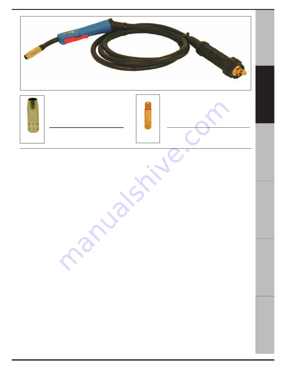
GAS NOZZLE
WIRE-FEEDER GUIDE
Fig.3
TORCH CABLE
EN
G
LI
SH
ES
PA
ÑO
L
РУ
СС
КИ
Й
FR
AN
ÇA
IS
DE
UT
SC
H


