23
IT
AL
IA
NO
4.
Connect (if present) the quick connector (
38 of
Fig 4B
) of the red tube to the quick coupler (
38
of Fig 4C).
5.
Connect (if present) the quick connector (
37 of
Fig 4B
) of the blue tube to the quick coupler (
37
of fig 4C).
6.
Connect the gas hose (
Fig 4B
) to the cylinder
(Fig 5)
by carefully following the instructions out-
lined in
Paragraph 7
.
7.
Take hold of the other end of the cable bundle
(
Fig 4A
).
8.
Connect the power electrical connector (
31
of Fig 4A
) to the appropriate coupler (
31 of
Fig 4C).
9.
Connect the signal connector (
30 of
f
ig 4A)
to
the appropriate coupler (
30
of
Fig 4c)
.
10.
Connect the quick connector of the black gas
hose
(32 of Fig 4A)
to the appropriate coupler
(32 of Fig 4C).
11.
Connect the quick connector of the red tube
(33 of Fig 4A)
to the appropriate coupler
(33 di
Fig 4C).
12.
Connect the quick connector of the blue tube
(34 of Fig 4A)
to the appropriate coupler
(34 of
Fig 4C.
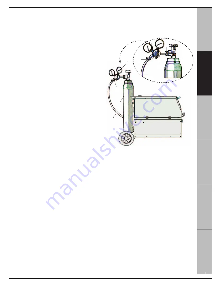
7. CONNECTION OF THE GAS CYLIN-
DER AND REGULATOR (see Fig 5)
1.
Connect the pressure regulator
(2)
to the gas
cylinder
(3)
.
Tighten the connecting nut
(6)
of the regulator
(2)
to the cylinder
(3)
.
Do not over-tighten because this may damage
the valve
(1)
of the cylinder
(3)
.
2.
Connect the gas hose
(4)
to the regulator
(2)
by securing it with a tube clamp
(5).
3.
Make sure the gas hose is correctly connect-
ed to the welding machine.
4.
Open the valve
(1)
of the gas cylinder
(3)
.
Press the torch button and make sure the gas
flows correctly.
Attention:
The cylinders contain highly pressurized
gas. Handle with care. Improper handling could lead
to serious accidents. Do not place the cylinders on top
of each other and do not expose to excessive heat,
flames or sparks. Do not allow the cylinders to strike
against each other. Contact your gas supplier for more
information on the use and handling of the cylinders.
Attention:
Do not use the cylinder if you find
oil leaks, grease or damaged parts.
Immediately contact your gas supplier if these
conditions exist.
8. MIG TORCH
It is recommended to periodically check the con-
dition of the welding torch. In particular, check
the gas nozzle
(Fig 3A)
and wire-guide tip
(Fig
3B)
. These parts must be kept clean and intact.
Replace the wire-guide when the wire does not
run smoothly.
9. PREPARING FOR THE WELDING
1.
Connect the welding machine to the mains
power.
2.
Make sure the polarity of the torch and ground
cables are positioned correctly.
3.
Connect the ground terminal to the workpiece,
making sure the contact is good.
Fig. 5
2
5
3
4
5
4
3
1
2
6
1
РУ
СС
КИ
Й
ES
PA
ÑO
L
FR
AN
ÇA
IS
DE
UT
SC
H
EN
G
LI
SH


