8
(LED 22 on) or pulsed
TIG mode (LED 23 on).
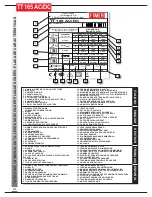
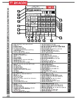
25. WELDING CURRENT KNOB.
Further Function: Turning this knob, while
using button 14 and LEDs 3 to 10, the
welding parameters can be set.
26. LOCAL / REMOTE SELECTOR:
Local (LED 27 off) or Remote (LED 27 on)
use of the welder can be selected pressing
this button.
When in local use the welding current is set
turning knob 25.
During remote use the welding current is set
using a remote unit (optional accessory).
27. REMOTE USE INDICATOR
28. BALANCE KNOB:
TIG AC welding:
The balance of the DC
component of the AC output welding current
can be set using thes Knob.
TIG DC/MMA welding:
Not used
29. Balance Current Confirmation:
TIG AC welding:
This lights up for app. 4
seconds at each setting selected using of
Knob 28.
MMA + TIG DC welding:
Not used
30. Direct polarity indicator
31. Reverse polarity indicator
32. AC mode indicator
33. Polarity selector:
Repeatedly pressing
this button alternates the output polarity .
MMA Mode:
switch between direct polarity
(LED 30 ON) (usual selection) and Reverse
polarity (LED 31 ON)
TIG Mode:
switches between Reverse
polarity DC mode(LED 31 ON) and AC
mode (LED 32 on).
34. Air-intake grills
35. Welding front socket
MMA welding:
Electrode clamp
TIG welding:
Welding Torche
36. Remote Control Connector
MMA welding:
Using a dedicated (optional)
accessory, the welding current can be
remote adjusted.
TIG welding:
A “start” or “stop” command is
relayed from the torch to the unit.
If a welding pedal (optional accessory) is
used, a suitable current level command is
also sent. (In the latter case, the torch button
is automatically disabled.).
37. Gas Hose Connector:
MMA welding:
Not used
TIG welding:
Torch hose connection.
38. Earth Clamp
MMA welding:
Earth Clamp
TIG welding:
Earth Clamp
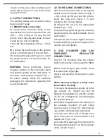
FIGURE 2:
39. Fuse
40. ON/OFF SWITCH
Switches ON or OFF
the unit
41. Power supply cable: Input cable
provided with plug.
42. GAS INPUT:
(Paragraph 5)
MMA welding:
Not used
TIG welding:
elding torch hose connection.
43. Liquid-Cooling System Connector
(optional accessory):
Beware !!
The connector uses dangerously high
voltage: NEVER use it for any other use than
as described in this Manual.
3. CONNECTION TO POWER SUPPLY
Before plugging the unit in, check the power
supply voltage, phase and voltage
frequency.
The permissible voltage is shown in the
“Technical Specification” chapter of this
manual and on the unit nameplate. Ensure
the welder is earthed appropriately. Also
check that the plug provided with the unit is
compatible with the local power grid socket.
Make sure that the power supply is sufficient
to operate the welder.
The types of power supply protection
devices to be used are listed in the
“Technical Specification” section of this
manual.
The power cable supplied with the welder
should not be extended but, if that becomes
necessary, either an identical or greater
cross-section cable should be used
according to the final cable length. The
TT165 AC/DC and TT205 AC/DC models
Summary of Contents for TT165 AC/DC
Page 1: ...InstructionManual TT165 AC DC TT205 AC DC TT165 AC DC TT205 AC DC ...
Page 4: ......
Page 5: ...TT165 AC DC TT205 AC DC ...
Page 10: ...X ...
Page 12: ......
Page 30: ...20 NOTE ...
Page 32: ...Cod 910 100 333GB REV00 ...


