Vibrator
1
A particular feature of this newly developed vibrator is its
easily calibrated impact interval of from 0.5 to 200 impacts per
minute.
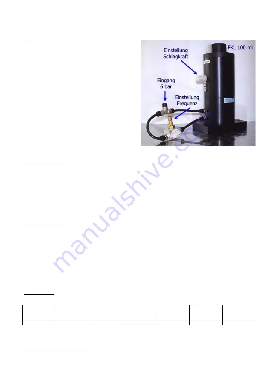
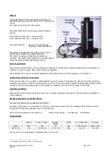
The impact force can be set to three levels.
Pneumatic impact force: Via the compressed air’s exhaust
channel.
Upper exhaust channel open = maximum force
Lower exhaust channel open = minimum force
Pneumatic frequency:
By means of a throttle valve
(included in supply specification)
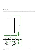
The vibrator is supplied with a base plate, which serves to
attach it and to transmit the impacts it generates.
The vibrator’s housing and base plate are made from
aluminium. The impact plate (integrated into the base plate) is
made from shock-resistant special plastic material.
Areas of application
Compressed air interval vibrators can be employed for knocking off material that has become attached to the inner surfaces of
containers (e.g. silos, hoppers, filter outlets, reactors and pipelines).
These vibrators can be used in wet surroundings and in those where there is a risk of explosion, or in the open air.
Construction and mode of operation
In the case of an FKL 100 mi, a piston is pushed against a spring by means of compressed air. Each time the piston passes the
compressed air outlet port, there is a rapid venting and it is shot under spring pressure against the impact plate contained within
the device. The piston valve then closes and the procedure is repeated at the speed set by means of the throttle.
Operating conditions
Reciprocating vibrators can be employed in dusty, wet or explosion-protected environments. Their piston seals are suitable for
oil free operation.
Standard installation for the FKL 100 mi
The drive mechanism is to be provided by the customer
Operation of the device can be controlled via a 3/2-way, normal/shut air valve. (Not to be confused with the interval, which is
set using the throttle valve supplied.) Hose of 6 mm diameter
The control mechanism can be by means of a:
- Process control system - Time lag relay - On/off switch
Technical Data
Pressure
Action / Impact
Impulse /
Impact
Weight Air
consumption
Frequency
Device
bars
Nm
Ns
kgs
litre / impact
impact / min.
FKL 100 mi
6 - 8
10 / 20 / 40
5 / 7.5 / 10
4.45
0.5 – 1.1
0.5 - 200
The FKL 100 mi can be employed for wall thicknesses of up to 5 mm
1
Set impact force; Inlet 6 bars; Set frequency
Operating instructions for FKL 100 mi
EM
02.07.2003
4300.00


