background image

                                                                                            4 

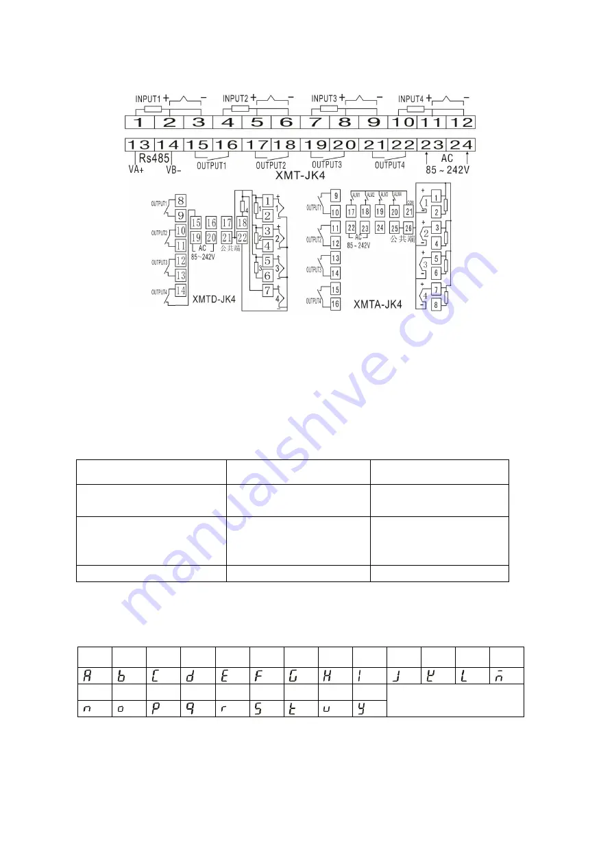
connection scheme(consult) 


Notice:

 The meter's signal input used to isolate type sensor, or that may affect the meter's 

measurement. 

Fault Analysis and Clearance 

XMT*-JK408 Series temperature controller adopt advanced production process, and have the 

strict test before leaving factory, it improve the reliability of the meter .The usual fault caused by the 

wrong operation or parameter setting. If you find the fault couldn’t be cope with, please record it, 

and contact with the agent or us. Sheet 8-1 is the usual fault of XMT*-JK408 series temperature 

controller in the daily application


Sheet8-1 Common fault disposal


Fault    symptom 

Analysis    of    causes 

Disposal    measurement 

Abnormal power 

1

Poor contact of power cord     

2

Power switch without lose 

Check the power 

Signal display do not correlate 

with the facts.

display ‘HH’or 

‘LL’


1

Sensor model mismatch 

2

Wrong signal connect ion 

1

Check sensor model and meter 

interior input parameter   

2

Check signal wire 

Abnormal control output 

Wrong connection of output wire 

Check output connection 

Note:


Our company will continue to improve product technology, design specification. If 

change, please subject to the


material object, without notice.


Attached 1

Statement of meter’s parameter attention letter and English letter 


www.finglai.com

Summary of Contents for XMT*-JK408 Series

Page 1: ... Cold end compensating deviation 2 3 Relay output contact capacity AC220V 5A resistance load or AC220V 0 3A perceptual load 4 Driving solid relay signal output driving electric current 15mA voltage 9V 5 Control mode difference control on off and PID control 6 Input power AC85 242V 50 60Hz 7 Environment Temperature 0 to 50 Humidity 85 RH Ⅲ Instrument panel instruction consult ALM1 ALM4 The first ch...

Page 2: ...ion alarm 4 negative deviation alarm 5 outside the interval alarm 6 inside the interval alarm 1 3 t Output cycle 0 120 S relay control action cycle setting 10 S 4 dp Display accuracy 0 1 1 have radix point 0 have not radix point 0 5 P SH The max value of temperature range P SH P SL They are used to reset proper temperature range as per user s application As for the Max temperature range for differ...

Page 3: ... and parameter value times will be shown respectively about CH1 window and CH2 window you can adjust these parameters by pressing and save the setting by press SET key every parameter should be saved after setting then enter next parameter set 6 3 You can press CH1 CH2 CH3 CH4 for 3 seconds to enter into corresponding channel menu After finished one parameter set press SET to save it then enter in...

Page 4: ...in the daily application Sheet8 1 Common fault disposal Fault symptom Analysis of causes Disposal measurement Abnormal power 1 Poor contact of power cord 2 Power switch without lose Check the power Signal display do not correlate with the facts display HH or LL 1 Sensor model mismatch 2 Wrong signal connect ion 1 Check sensor model and meter interior input parameter 2 Check signal wire Abnormal co...

Reviews: